       task 1      task 2      task 3      task 4      task 5
      $100-132    $133-165    $166-198    $199-1CB    $1CC-1FE
It will be clear enough how to divide it into different numbers and sizes of segments. If you know ahead of time roughly how much
stack space each task needs, you might be able to allot different sizes of stack segments for each, allowing more tasks because ones that
don't need much stack space don't take it away from the ones that do. I expect that with care, you could in many cases safely do
several more tasks than that.
Each task's stack pointer will be restored to it when it gets its turn to run again, taking its position from the appropriate variable which you load into X and then transfer to the stack pointer with TXS; and at the end of its turn to run, the reverse will be done to store the position away for the next time it runs. (If you have one or more separate data stacks in ZP or elsewhere in memory, those will need to be handled similarly.) If there's an actual OS handling the multitasking, its stack pointer will need to be saved and restored too. (For simple ways to do multitasking without a multitasking OS, for systems that don't have the resources to run such an OS, or where hard realtime requirements may rule one out anyway, see my related article.)
What Jonathan Halliday is doing in his preemptive multitasking GUI OS for Atari 6502 computers (a few paragraphs down) allows more stack space than meets the eye, by leaving the major tasks' stack space in place full time, but moving stack memory for low-priority tasks so several of them can use the same portion of page 1, effectively expanding it. He writes, "This is where scheduling strategies can become densely complex. If the scheduler wants to context-switch to a task whose stack frame is cached out, it looks for sleeping tasks to evict. If it finds one, it then looks for the lowest-priority task currently using the stack and evicts that instead. Of course that sleeping task could just be on the verge of waking up in the next system tick, but there's a compromise to be found here, and too much complexity will just slow everything down anyway." The user-interface process has the highest priority of all, ensuring that the UI updates remain fast.
On the NESDev forum, lidnariq posted, in the topic "6502 cooperative multitasking framework" a fascinating little chunk of code he found while reverse-engineering a dot-matrix impact printer's firmware. He writes, "Yield saves A,X,Y,S, and PC of the calling thread and switches to another thread. The scheduler appears to just be round-robin; if thread N yields, thread N+1 is resumed ... until all threads have yielded, in which case they're all marked as 'allowed to execute' again and it resumes with the first one in the table. Specifically, this was running on a Mitsubishi 740-class microcontroller, which uses a superset of the original NMOS 6502 instruction set, and has many of the same instructions (although with different encodings) as the WDC 65C02." See the code at the link.
On the Codebase 64 Commodore 64 site, Gregg has a short article called Threads on the 6502 where he writes,
In this example two threads will be initiated which will use different stack areas. Using a round-robin scheduler running in an irq (context_switch) these threads are run one after the other. The thread data is stored on the stack, suitably for RTI, so you only need to manually push the register (A, X, Y) values. In the end it comes down to adjusting the stack pointer for each thread. The stack pointer of each thread is stored starting at thread_data.
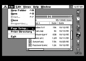
Related, see the preemptive multitasking GUI OS for Atari 6502 computers. At
the time of this writing, it is not finished yet, but here are a couple of screenshots provided (I'm sure Jon won't mind my giving him free
publicity):

![]()
A little bit from the page:
<snip>
The completed graphical OS will include:
Is it really pointless to try something like this on a 6502 in 2015? I am attracted to the related philosophy in the articles
of a very sharp, experienced professional programmer, Samuel Falvo,
"Software Survivalism" and
"Neo-Retro Computing." And although I have not had
any exposure to 6502 Atari computers, I am fascinated by the discipline and care and inventive techniques used to pull this off in a
system with such limited memory and execution speed. It's definitely a good practice, and forces one to be more efficient with the
resources. It's a valuable skill to transfer to any system, including modern ones where bloatware and programming
sloppiness are unfortunately the norm. Today as I write this, our son's smart phone crashed, and took several minutes to
re-boot. Why did it crash? Bugs. Why did it take so long to re-boot? Bloat. My hat is off to Jonathan Halliday,
and also to Paul Fisher, Jörn Mika, and others I might have missed who contributed to his (so-far-nameless) Atari multitasking GUI OS!
        TSX
        PHX
        LDA  #<stack_origin>
        SEC
        SBC  100,X            ; Note!  Not 101,X!  (PHX came after TSX.)
        PLX                   ; We're done with this on the stack, so drop it.
                              ; The result excludes the stack byte we kept X in.
If you have a ZP data stack and are using X as its pointer, the above will require saving and restoring X also, something like:
        PHX
        TSX
        PHX
        LDA  #<stack_origin-1>   ; The -1 is because we first pushed
        SEC                      ; X as our data-stack pointer.
        SBC  100,X
        PLX
        PLX
In both cases, the result at the end is in A, and you can push that to the stack after the code fragments above if you need to. Also
in both cases, the result tells the number of bytes. (On a data stack like below, the depth is normally reported as the number
of cells, and there may be two or more bytes per cell.)
Assuming you use X or Y for a pointer into a virtual stack which gets a lot of attention in this treatise, the pointer
is a little more directly accessible, but unfortunately you still can't subtract it directly, but you can temporarily store it elsewhere:
        DEX
        TXA
        STA  0,X
        LDA  #<stack_origin+1>   ; The +1 is because we first did
        SEC                      ; did a DEX.  (See note below.)
        SBC  0,X
        INX
This gives the number of bytes. If you want the number of 2-byte cells, follow it with an LSR.
You could leave out the DEX and INX and shorten it a bit if you can be sure an
interrupt won't overwrite the stacked pointer value:
        TXA
        STA  $FF,X               ; This should give a ZP addr mode.
        LDA  #<stack_origin>
        SEC
        SBC  -1,X
But here's the more-efficient method I said was coming. It's a less-obvious solution, but shorter and quite a bit faster:
        TSX
        TXA
        EOR  #$FF
        SEC
        ADC  #<stack_origin>
In all cases, you can leave out the SEC if you know the carry flag will already be set when arriving at this part
of the code.
So why measure the stack depth? After all, once you get the hang of stacks, it's rather uncommon to accidentally over-
or underflow a stack even in development, and the danger is almost completely non-existent after that, so there's really no point in adding the
overhead of always checking. Well, actually, even with no such danger, there are good reasons to get the stack depth.
One application I've used in Forth extends the CASE structure's capabilities with
SET_OF (and also RANGE_OF). I think I got the idea from Forth Dimensions magazine in the 1990's. A
{ (left curly brace) checks the data stack depth and stores it temporarily, and the } (right curly brace) checks the data stack depth again and
returns the difference. SET_OF uses the difference which } puts at the top of the data stack to know how many
numbers to compare to.
   CASE
                    0A         OF  <do_stuff>  END_OF   \ In the case of it being 0A, do this.
                    0E         OF  <do_stuff>  END_OF   \ In the case of it being 0E, do this.
        { 13 41 5B 20E }   SET_OF  <do_stuff>  END_OF   \ If it's one of these numbers, do this.
                15  28   RANGE_OF  <do_stuff>  END_OF   \ If it's in the range of 15 to 28, do this.
   END_CASE
In another use, I had a situation where I wanted to type on the command line a list of numbers to be handled, and automatically
allow varying numbers of inputs, then calculate a table of gear ratios and accompanying info and print a chart:
DECIMAL
   {  6  7  8  9 18 19 }  DON'T_USE
   { 12 13 14 15 17 19 21 23 25 }  { 30 42 52 }  CALC_GEARS
HEX
The DON'T_USE (note that Forth allows using almost any character in names) set of ratios was to be left
out of the calculations because of undesirable chain angles. (This was for bicycle gearing.) Note that since the } puts a depth
number on the data stack, you can have one group after another, as long as you don't run out of stack space, and the routine that handles them
can make sense of it. There will not be any errors from having a wrong number of parameters on the stack. The 12...25 sequence shows
the numbers of teeth on each cog of a 9-speed cassette, but it could just as easily be a different number of cogs, say 8 or 10; and the 30...52
sequence shows the numbers of teeth on each of three chainrings, but it could just as easily be two chainrings. So
DON'T_USE and CALC_GEARS could just as easily handle the following, even though the numbers of parameters
are different:
DECIMAL
   {  9 10 11 12 }  DON'T_USE
   { 12 13 14 15 16 17 19 21 23 25 }  { 39 53 }  CALC_GEARS
HEX
Since it's all stack-based, the following would work the same (but it would be less intuitive):
DECIMAL
   { 12 13 14 15 16 17 19 21 23 25 }  { 39 53 }   { 9 10 11 12 } DON'T_USE  CALC_GEARS
HEX
Right before the DON'T_USE, there would be 19 cells on the data stack in this case (plus any that were there
before this line); 16 for the numbers in the three groups, plus one on top of each group, telling its size. DON'T_USE
removes the top 5 and puts them in an array, and CALC_GEARS removes the rest and prints the chart.

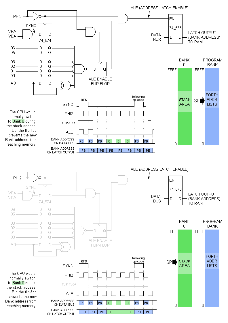
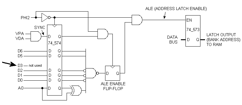
The version below lets RTS and PLA both pull from the program bank:

Basically, Forth runs in a non-0 bank, and most of bank 0 must be left available for the hardware stack, since it will not be known what
the value in the Forth program counter (IP, held in register S) is when an interrupt hits. Stack operations
relating to the interrupt will write to and read from bank 0, while RTS serving as Forth's
NEXT reads the bank that the program is in, rather than bank 0 where the hardware stack resides. See the forum
topic for explanation and discussion. What was not
discussed was how the Forth words that access the return stack would work, for example do, ?do, loop, +loop, leave,
?leave, unloop (ie, the internals compiled by DO, ?DO, LOOP, +LOOP...), I, J, >R, R>,
and R@.
blargg has an interesting write-up on using S as an index register in a sense for transferring a small buffer of data (small enough to fit in the available hardware stack area) to or from an output device. Pushing or pulling the data is faster than using X- or Y-indexed addressing and incrementing or decrementing X or Y. X and Y are both now left free for other uses. The lack of any kind of handshaking or status-checking might rule it out for most applications, but see if it gives you any ideas.
This example quickly outputs a buffer of 0-terminated stacked data to a memory-mapped device outside of ZP. Each byte takes 11 cycles to
read from the buffer and output:
        LDA  #0
        PHA             ; Push nul terminator first.
        ...             ; Now push the data

        <When it's time to output the data, jump to "next" below.>

read:   STA  port
next:   PLA
        BNE  read
This next example quickly reads data from a device and stops when it receives a 0. Each byte takes 10 cycles to input and write to the
buffer:
        TSX             ; Save the current stack pointer.
        STX  end

write:  LDA  port       ; Read from the device
        PHA             ; and push the byte.
        BNE  write      ; Drop through when you read a 0.


read:   PLA             ; Jump here when it's time to read the data.
        ...             ; Use the data.
        TSX
        CPX  end        ; Keep checking the stack pointer value
        BNE  read       ; and drop through when we've reached it.
By putting the buffer at the bottom of page 1, S can be used as both a counter and an index for a write buffer. Each byte takes 12 cycles to input
and write to the buffer:
        TSX             ; Save the stack pointer.
        STX  stack

        LDX  #size
        TXS

loop:   LDA  port
        PHA
        TSX
        BNE  loop

        ...             ; Use the data.
        LDX  stack
        TXS             ; (He had TSX, but I fixed it.)
By putting the buffer at the top of page 1, S can be used as both a counter and an index for a read buffer. The normal stack would need to
be placed lower in page 1 to coexist with this scheme. Each byte takes 13 cycles to read from the buffer and output:
        LDX  #0         ; Init stack.
        TXS

        ...             ; Push data on stack.

loop:   PLA
        STA  port
        TSX
        BNE  loop
Here is another floating-point library, in source form, by Carol Shaw, from 1979 (ie, for NMOS 6502), as well as the calculator source.
Features:
The calculator requires 24K of RAM.
17. forming program structures <--Previous |
(Next--> 19. further reading)
last updated Jul 15, 2020