The 6502.org forum topic "Multi tasking?" has many good considerations regarding multitasking on a 6502, and links for more help, including to additional forum topics and other resources on the web. Do read through that topic (which is in its fourth page now). Rather than repeating that material here, I want to cover three simple methods I've used (sometimes in combination) that have effectively prevented the need for a multitasking OS of any kind, in my applications.
In addition to these three, I'll mention a fourth one for comparison: preemptive (or pre-emptive) multitasking. To dramatically simplify the differences between the methods mentioned here:
Often what is thought of when we mention multitasking is preemptive multitasking operating systems. "Preemptive" means
there's a timer that produces an interrupt for the OS to preempt, or take control away from, the currently running task, and get another task
going wherever it left off last. It basically says to the currently running task, "I don't care what you're doing, or how heavily involved
you are in it, you're done!" No Mr. Nice Guy. No "Find a good stopping point and report back as soon as is practical." The
OS takes up the job then of saving the things the task will need for its continued execution the next time it is given a chance.
Preemptive is the type of OS often thought of when we mention "multitasking," possibly for reasons including (but not limited to):
My earliest work example of a realtime design was a high-end intercom for private aircraft in 1993 whose separate user control module depended on pulse lengths generated by software in the 65c02 computer, which were governed by interrupts from its 65c22's Timer 1. If something were to delay the timer interrupts, this control head would not work. In a crude but valid way, due to the interrupts, the system could be considered at least dual-tasking; the task of feeding the control module the needed signals and watching the info it sends back, and the "everything else" task which babysat a lot of intercom functions in a loop, functions whose timings weren't as critical. Actually, this main loop did call the various functions as subroutines (or more or less as tasks), but my code organization was still poor back then, and looking at my code for it now, I do not find it intuitive to figure out what each one should do under various conditions each time it runs. In a minute I'll address separating the tasks and making them like state machines, more structured, more clear, and easier to debug and maintain, without using a multitasking OS.
Another example where interrupts cannot be delayed by task switches would be audio sampling at a rate of tens of thousands of evenly spaced samples per second, timed by interrupts, in the absence of a sound card and its associated DMA and buffering. Having even an extra couple of instructions' delay before an interrupt vector is taken makes for unacceptable jitter and its resulting noise and distortion. (I have a discussion on jitter here.)
Unlike a PC, my workbench computer exists not for human interface, but for controlling things on the workbench, taking data, etc.. Its whole raison d'être centers around having very immediate access to the hardware; so it would be unacceptable in this situation to have an OS that requires that programs go through OS calls to gain access to the hardware. Access could be through a single sub-microsecond instruction to write to a port for example.
I have not had to deal with problems like mutual exclusion, because so far, in my embedded systems, I have not had situations where different tasks wanted access to the same resources at the same time, nor mass-storage file systems, although I can imagine contentions on 65SIB devices; e.g., that one rather high-priority device may cause an interrupt while another device is getting fed a stream of bytes that cannot be interrupted unless you start over when you come back to it. If this keeps happening, the transfer would never get completed! The bus spec does have a provision to put a device on hold without de-selecting, but I have not gone that far with it myself.
These multitasking methods require tasks to be of the RTC type. "RTC" in this case stands for "run to completion," not "real-time clock" (although a real-time clock will usually be involved too, so the terms will mostly be spelled out instead of abbreviated). This is because a task's program pointer and anything it might have on a stack is not preserved from one run of the task to the next run of the same task. Obviously then, the task has to finish up with the stack before giving up control, and leave it as it found it; and, if it matters what part of the task the computer jumps into the next time the task runs, the task will have to keep a record of that for itself, because there's no OS there to do that job for it. It is generally simpler and more efficient if the task can do this for itself anyway.
Particularly in the cyclic executive, "run to completion" does not mean the entire task runs, or that it has nothing left to do when
it returns, but rather that it runs until it finishes what it needs to do at the moment, and it returns when it reaches a good stopping
point. This eases the job of switching tasks and picking up where it left off again the next time it runs. As we'll see in a minute,
usually only a small portion of a task's entire code will run each time the task is called; but it will be the correct portion for the current
situation.
The purpose of the interrupt is of course to let the main program(s) run freely and efficiently, not having to keep checking to see if a super-urgent need has arisen, yet be able to service that need immediately when it does arise— with much better response time than it could if it kept checking for it. Servicing ports on demand or doing another program portion on a schedule dictated by a hardware timer are examples of how the computer can appear to be doing more than one thing at a time. The 6502 has outstanding interrupt performance. Take advantage. There's plenty on these things in the interrupts primer; but here I want to put further attention on using interrupts for a real-time clock which will be used in the cyclic executive method further down.
I've been using a VIA's (6522's) T1 timer for a software real-time clock. It interrupts every ten milliseconds to increment the timer bytes as shown in the code in the article. This real-time clock is a necessary component for many tasks, and a one-second (or even one-tenth-second) resolution that you might find on some hardware real-time-clock products is definitely not adequate in this case. Many applications have no need for time-of-day or date functions, but there's still the need to time key debouncing, beeps, looking for time-outs on other interfaced equipment, and other things that need to be timed. Software timing loops for delays are not acceptable because the computer has far too much to do to be stopping and twiddling its thumbs for the duration of the delay— and that's especially true when it must time several things at once. This will get more attention in the "Cyclic executive" section further down.
Interrupt-service routines (ISRs) of course are always of the run-to-completion type. They must return the stack and possibly other things to the interrupted program such that it has no idea anything happened; otherwise ISRs would be fouling things up royally. However, no help from an OS is needed for keeping the address to return to after the ISR is done, or to restore the processor status register at the end, as these are part of the interrupt sequence and the RTI instruction. The ISR does need to stack and restore the other processor registers it uses though, so as to return them to the other routine the way the ISR found them. On the 6502, these would be A, X, and/or Y. (Don't make the ISR waste time saving and restoring registers it does not use though, just as you shouldn't waste time polling for interrupt sources that aren't even enabled.)
The 6502 interrupts primer has lots more on interrupts,
including example code and circuit info. Also, as a follow-on to that, BDD has a 65816 interrupts article, at
http://sbc.bcstechnology.net/65c816interrupts.html,
also found on 6502.org at
http://6502.org/tutorials/65c816interrupts.html. Toward the
end, he goes into things relating to preemptive multitasking OSs and implementing an execution environment that prevents user programs from
affecting each other or an OS kernel, with the development of a protected environment not unlike that of a commercial multiuser
system. Although he does not delve into OS design, he does discuss the basics of using the kernel trap software engineering technique to
implement an OS application programming interface (API) on a 65816 system.
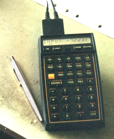
My inspiration for alarms came from the time functions on my HP-41cx calculator/computer which allows various kinds of alarms.
These days, its alarm functions get used for little besides getting me up in the morning with its beeps; but you can also have it execute a program when the alarm comes due. The calculator's timer hardware can even wake the calculator up when an alarm comes due, start running the program specified by the alarm, which can do countless control functions and take data from lots of instruments on the workbench, log it, print it, etc., and even put itself back to sleep when done. The coming-due of an alarm can also interrupt the running of another program, acting as an interrupt. Many pending alarms can be held in a queue at once.
You could have a hardware timer incorporating a comparator that watches for a match and causes an interrupt; but what I've always done is to use the software real-time clock (which runs on interrupts from a 65c22 VIA's T1), adding a portion of code to do the comparison and then act if there's a match. It adds very little execution time to the real-time clock ISR, for two reasons:
Your alarm-management software can of course keep, install, delete, and sort (by due times) many alarms, and any given alarm's
routine might also set an alarm for the next time it's supposed to run. It might be to collect new data every second, every minute, every
fifteen minutes, or whatever. I'm using a 10ms resolution, meaning I could conceivably have as many as 100 alarms per second and schedule
something up to 2^32 centiseconds (over 16 months) out.
I don't think I've ever scheduled any that fire really fast, but one recent application on the workbench was to test battery life on a new product, taking battery voltages, and, every 15 minutes, printing out the accumulated run time, the current battery voltage, the lowest battery voltage seen over the last 15 minutes (because the load is not consistent), how fast the low-battery LED was flashing (since it is designed to flash faster and faster as the batteries weaken), and whether the product had shut itself down yet because the voltage was too low. Then I was able to use the workbench computer for something else at the same time, with my other program not having to know it wasn't the only one running. I was experimenting with something else and developing code for that, and every fifteen minutes, the printer pounded out another line of battery data. 20+ years earlier, I did a similar thing with the calculator shown above, having it connected to a data-acquisition unit and a printer.
If there's a risk of having multiple alarms with the exact same due time, a few possible ways to deal with it are:
The real-time clock ISR in the 6502 interrupts
primer could be augmented this way. (cs_32 is the name of the centiseconds' 32-bit (four-byte) variable.)
                                ; NMI vector points here.  Usually very few instructions
INCR10ms: PHA                   ; get executed.  Save A since we'll use it below.
          LDA  VIA1T1CL         ; Clear VIA1 interrupt.

          INC  cs_32            ; Increment the 4-byte variable cs_32.
          BNE  INC_TOD          ; If low byte didn't roll over, skip the rest.

          INC  cs_32+1          ; Else increment the next byte.
          BNE  INC_TOD          ; If that one didn't roll over, skip the rest.

          INC  cs_32+2          ; Etc..
          BNE  INC_TOD          ; (More than 99.6% of cases will skip out after
                                ;  the first test.)
          INC  cs_32+3

INC_TOD:              ; The keeping of the time of day and calendar will be skipped here
                      ; for brevity, and we move on to the alarm-watching, doing it on
                      ; the centiseconds bytes, not the time-of-day and calendar bytes.

CK_ALM:   LDA  ALM_XEQ_ADR + 1  ; If there's no alarm pending (shown by a 0 in the high
          BEQ  CkAlmEnd         ; byte of the addr of its routine, then just exit.

          LDA  cs_32            ; Compare the low byte of the time to that of the next
          CMP  ALM_cs_32        ; alarm.  If it doesn't match (as will nearly always be
          BNE  CkAlmEnd         ; the case), then just exit.

          LDA  cs_32     + 1    ; Check the second-to-lowest byte,
          CMP  ALM_cs_32 + 1
          BNE  CkAlmEnd

          LDA  cs_32     + 2    ; the next,
          CMP  ALM_cs_32 + 2
          BNE  CkAlmEnd

          LDA  cs_32     + 3    ; and finally the high byte.
          CMP  ALM_cs_32 + 3
          BNE  CkAlmEnd

          JMP  (ALM_XEQ_ADR)    ; If the time matches that of the next alarm, go to the
                                ; routine specified with the alarm, which should end
CkAlmEnd: PLA                   ; with JMP ALM_END which deletes the alarm and moves the
          RTI                   ; next one into position in the array, restores used
 ;------------------            ; registers (ending with A), and does RTI.
If there's no alarm pending, the RTC NMI ISR will usually take 8 instructions, including the RTI. If there
is at least one alarm pending, it will usually take three more instructions. Comparison is done on the low byte first and high
byte last to save cycles, since the high bytes are more likely to be the same. Where my setup goes over 16 months, if my alarms are typically
for the same day, the high byte will usually match, requiring more byte comparisons in order to see that we're not there yet; so that's not the
place to start the comparison.
The alarm array might look something like:
ALM_LIST:    DFS  8*6         ; DFS ("DeFine Storage") in the C32 assembler makes a
ALM_cs_32:   EQU  ALM_LIST    ; variable space of that many bytes.  Here we're leaving
ALM_XEQ_ADR: EQU  ALM_LIST+4  ; room for an 8-alarm queue, each having 4 bytes for the
                              ; cs-32-matching time and 2 for the alarm-execute address.
                              ; ALM_cs_32 and ALM_XEQ_ADR are for the first one in line.
In my 6502 Forth system, the alarms essentially activate a Forth ISR, which, as shown in the article on that subject, really has no overhead. As you might imagine, there are many ways to carry out alarm methods. You might have routines to:
How complex you want to get is up to you of course. These are merely suggestions, based on what I have running in Forth.
Certain things in your tasks may be inappropriate to time with alarms though. Take for example a key-scanning
routine. Debouncing is always needed, and often done poorly. After the routine sees that you've pressed a key, it needs to wait to
see if it finds it pressed for 50ms in a row before submitting it to the other routines as a valid keypress. Do not set an alarm
for 50ms later. The task needs to be run many times in that amount of time, making sure the key remains pressed for 50ms in a row, and
it should re-start the count every time it sees the key up and then down again. This constant re-checking does not need to be on any
particular schedule though. There's little difference between getting to it every 100 microseconds versus every 2 milliseconds, while
taking care of other tasks in between these checks. That's one of countless scenarios that are better done with the cyclic executive
method below.
"State machine" basically just means the task uses a variable to keep track of what part of the routine to route execution to the next time the task is called from MAIN_LOOP. The state number is held in the variable, and depends on what the task was doing last, and may get changed ("transitioned" to another state) when it has finished something, or when an event or clock time that it was watching for arrives, dictating that we're moving on to the next step, or perhaps to start over.
The beginning state is 0. The state may remain unchanged for long periods while the task is waiting for something; and in that case, the same little part of the task code keeps getting run every time the task is called. As long as it sees that the awaited event or time has not arrived yet, it just exits without doing anything. When the event or time finally does arrive, the task takes the appropriate action, and transitions to another state. A transition often consists of incrementing the state to the next higher number; but there are a lot of exceptions where it may get changed to something else.
You can do a cyclic executive with any processor. I'll describe it here. I started with this kind of thing:
MAIN_LOOP:
      BEGIN
          JSR  <task_1>
          JSR  <task_2>
          JSR  <task_3>
             <etc.>
          JSR  <task_n>
      AGAIN
(The BEGIN...AGAIN is one of many structures I present in my website
section on structure macros, at
http://wilsonminesco.com/StructureMacros/.)
On the PIC (whose subroutine-call instruction is CALL, not JSR), this was in ROM, and the task list did not change; but you could put it in RAM on the 6502 if you like, and adjust the list as you add or remove tasks. If you do put it in RAM, the task at the top of the list should probably be the one that adjusts the list, adding new tasks or deleting ones that are no longer needed. After deleting one, it can either move the following ones up to fill in the spot, or replace it with NOPs. (BTW, if you need to fill in byte pairs with NOP NOP, let me recommend LDA/X/Y#__ instead, using any register you can spare, as it takes only two clocks instead of four.)
Since my processing power was limited, and a couple of the tasks needed a bigger share of it than others, I put their subroutine calls in the main loop twice each, distributed such that they would never have to wait too long between runs. The main loop then would look something like this (note tasks 1 & 2, each called twice in the loop):
MAIN_LOOP:
      BEGIN
          JSR  <task_1>
          JSR  <task_2>
          JSR  <task_3>
          JSR  <task_4>
          JSR  <task_5>
          JSR  <task_1>  ; (repeated, to get a greater share of the processing time)
          JSR  <task_2>  ; (repeated, to get a greater share of the processing time)
          JSR  <task_6>
          JSR  <task_7>
          JSR  <task_8>
      AGAIN
The tasks I had were all dependent to some extent on time, or on other things having completed (like a byte being shifted in or out on a slowish hardware serial interface), or on a flag being set to indicate whether the task was active at the time, or something like that; so each one might:
There may be variations, depending on your application. Many tasks will have little or nothing to do most of the times they're
called, so they take very little time. Some tasks won't be activated at all for long periods of time, so they exit immediately. Such
a task might first test a flag variable to see if it's even supposed to be active at the moment, and if not, return immediately. The entire
time it takes then is only the JSR<task>, BIT<variable>,
BMI, RTS, only 18 clocks, including the JSR and
RTS.
For an example of a task that watches for a time on the clock, consider a task whose job it is to put a battery icon in the lower-right corner of a 2x16 intelligent character LCD, with the battery state being shown by how full the icon is, and when the battery gets below a certain level, make the icon blink with a one-second cycle, regardless of other tasks running. (I've done a similar thing with an LED where the first indication comes when there's one-third of the battery life left, and the blink rate increases as the battery voltage continues to drop, giving a pretty good idea of how much life is left. We'll avoid that complexity for this example though.) These LCDs, available from many manufacturers, all use the same instruction set (and have for 35+ years— how's that for stability!), and they allow making your own custom characters in a 5x7 dot matrix. A custom character of a battery works out nicely. (I have 6502 sample LCD code here.) We will take a battery voltage measurement twice per second, matching the rate the icon turns off and on if it's supposed to blink.
BATT_STAT_DISP_TASK:
      <take current clock time>
      <subtract the target time>
      <RTS if result is negative meaning we're not there yet>

      <add 500ms to the target time variable telling when to check battery next>

      JSR  GET_BATT_STAT                      ; (Number comes pre-processed, in the range of 0-5.)
      CMP  #2                                 ; (Threshold for blink.  0 & 1 blink, 2 thru 5 don't.)
      IF_MINUS                                ; If it's low enough to blink,
          IF_FLAG_VAR  BATT_DISP_FLAG, IS_SET ; and if the battery display is on right now,
             LDA  #$20                        ; just get ready to replace it with a space,
             CLR_FLAG  BATT_DISP_FLAG         ; and record that the battery display is off now.
          ELSE_                               ; The ELSE is if it should blink, and it was off (ie, a
             SET_FLAG  BATT_DISP_FLAG         ; space); so just record that we're blinking it back on.
          END_IF                              ; Otherwise the level in A from above will be the
      END_IF                                  ; pseudo-ASCII (custom character).
                                                         ; Now show it, either the battery icon (at
      <save cursor position (whether visible or not)>    ; the right charge level) or a space.
      <set cursor to chr position of battery icon>
      <send the character specified above (00, 01, 02, 03, 04, 05, or $20) to LCD>
      <restore previous cursor position>

      RTS
 ;------------------
The reading from GET_BATT_STAT above is the character code to send to the LCD as if it were ASCII, (0 for a
nearly dead battery, up to 5 for a practically new or fully charged one), after you have defined the six custom characters' dot patterns to
display. The LCD lets you have eight at a time, with character codes 00 through 07. For the picture below, I did the six battery
states on my workbench computer's LCD just to quickly make them all show
at once for a photo:
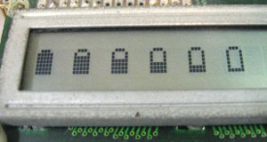
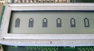
On the left, the Icons are five dots wide, and on the right, four. I also tried three but it turned out looking more like a baby bottle. (Pardon the corroded bezel. The LCD is 27 years old!) If your application doesn't need more than eight custom characters, you could probably define them all in the reset routine and leave them alone after that. The Forth code that I used for the pictures above is at the end of the sample LCD driver code, at http://wilsonminesco.com/6502primer/LCDcode.asm. It's the only part of the file that I don't also have in 6502 assembly. It just took a few minutes to write, an instant to compile on the workbench computer in spite of an unrelated application loaded that was still in use, and it worked on first try— which is partly why I use Forth a lot.
Regarding the target time variable which might be called BATT_DISP_TM for example: Although 8 bits may be enough to make the blink rate appear steady, a cyclic-executive multitasking application of this type will probably have you using 16-bit routines for doing transfers and calculations of times for other routines, even if the RTC uses more. (You can select which bytes of the RTC to use, e.g., bytes 0 and 1, 1 and 2, or 2 and 3.) The target value should be initialized in the reset routine to prevent super long delays before the first blink, if the icon ought to blink.
Now let's look at a couple of examples of using a state variable for the task to know what to do each time it is called, rather
than just going from beginning to end.
First is a relatively simple one. Suppose:
 ; For the RX_STATEs:
 ; When RX_STATE = 0, an $FF byte will be required to increment RX_STATE to 1.  Other bytes do nothing.  The $FF is discarded.
 ; When RX_STATE = 1, only a non-$FF byte will be put in READING_BUF and increment RX_STATE to 2.  More leading $FF's do nothing.
 ; When RX_STATE = 2, any value received will be put in READING, READING_BUF will be transferred to READING+1, and RX_STATE will
 ;                                                                                                               be returned to 0.


WATCH_ACIA:
      LDA  RX_STATE
      CASE  ACCUM

          CASE_OF  0                             ; In the case of RX_STATE being 0, an $FF is required to increment it to 1.
              IF_BIT   ACIA_STAT_REG, 3, IS_SET  ; If a byte came in (indicated by bit 3 of the status register),
                  LDA  ACIA_DATA_REG             ; get it (this clears the flag in the status register too),
                  INA                            ; and see if it's $FF.  (INA is 1 byte less than CMP #$FF, and I don't need A again.)
                  IF_EQ                          ; If it was $FF,
                      INC  RX_STATE              ; move on to watch for a valid (non-$FF) first byte.
                  END_IF                         ; The accumulator value gets discarded.
              END_IF                             ; If no byte came in, just exit.
          END_OF


          CASE_OF  1                             ; To get here, we've received the $FF marker and we're looking for a valid 1st byte.
              IF_BIT   ACIA_STAT_REG, 3, IS_SET  ; If a byte came in,
                  LDA  ACIA_DATA_REG             ; get it,
                  IF_PLUS                        ; see if it's valid as a high byte, ie, that the high bit is clear, and if so,
                      STA  READING_BUF           ; store it as valid in the buffer area meant to prevent wrong readings between bytes,
                      INC  RX_STATE              ; and move on to watch for the 2nd byte which could be anything.
                  END_IF                         ; If it's not a valid high byte, just discard it, and leave RX_STATE as is.
              END_IF                             ; If no byte came in, just exit.
          END_OF

                                                      ; In the case of RX_STATE being 2, we've gotten the high byte of READING,
          CASE_OF  2                                  ; and we're waiting for the second byte which could be anything.
              IF_BIT  ACIA_STAT_REG, 3, IS_SET        ; See if a byte came in.  If one did,
                  COPY  VIA_SR, TO, READING           ; just transfer it
                  COPY  READING_BUF, TO, READING+1    ; (including the high byte now, which we had saved to prevent glitches
                  STZ   RX_STATE                      ; in the two-byte READING value), and go back to state 0.
              END_IF                                  ; If no byte came in, just exit.
          END_OF


          STZ   RX_STATE                         ; If there's any chance for state to go invalid, just reset it and start over.
      END_CASE
      RTS
 ;---------------------------------------
Since there has been discussion on the 6502 forum about WDC's 65c51 bug, I should mention that doing tasks of this type is a good way to give the needed delays and still get other things done while waiting. This one uses both a state variable and target times to know what to do each time it is called. The WDC 65c51 bug is that bit 4 of the status register is stuck on, making it look like the byte you gave the ACIA has already gone out and it's ready for another one when actually that's not true, and writing too soon would make bytes get lost. Until the bug is fixed, the way to prevent an overrun is just to delay the required amount of time before giving it another byte. The common way to do this is to just use a delay loop; but then the computer can't do anything while waiting. It would be better to use a task in the cyclic executive that goes something like this:
ACIA_XMT_TASK:                                ; (Don't confuse TX_STATE and TX_FLAG.)
      LDA  TX_STATE                           ; We'll first check for the case of TX_STATE being 1, ie that we're
      IF_NOT_ZERO                             ; looking for the end of the delay, even if there's not another byte
          <get the current time>              ; to send yet, to prevent problems with time wrap-around and possibly
          <subtract the target time TX_TM>    ; resulting in long delays when the next byte is available to send.
          RTS_IF_MINUS                        ; Just exit if it's not time yet.

          STZ  TX_STATE                       ; If the delay is over, reset the state to skip this part of the
      END_IF                                  ; code next time.

      RTS_IF_FLAG_VAR  TX_FLAG,  IS_CLEAR     ; If there's nothing to transmit right now, just exit.

                                              ; If we got here, it's because there's something to transmit,
      CLR_FLAG  TX_FLAG                       ; and it's safe.  Indicate that we're taking the byte.
      LDA  TX_BYTE                            ; Take it
      STA  ACIA_DATA_REG                      ; and send it.

      <get current time>
      <add the amount of time needed to shift a byte out at the current speed>
      <store the result in variable TX_TM>

      INC  TX_STATE                           ; Record that the next time through is to monitor the delay.
      RTS
 ;------------------
Details on the time will depend on the resolution in microseconds and the number of bytes you use for time. 10ms resolution like I have on the workbench computer's interrupt-driven real-time clock won't be adequate. Reading T1's high byte could be made to work, but reading T1 low may occasionally have the undesirable effect of clearing its interrupt at the perfect wrong time. Project A spoken of here had a resolution of approximately 40 microseconds. Project B's was about 25. (Another way to handle it would be to get an interrupt from a VIA timer in one-shot mode, and set the timer every time you give WDC's ACIA a byte to transmit.)
Now we'll look at a more complex example, one for key-debouncing and repeating mentioned earlier, for a 16-key (4x4) keypad,
for project B. Translating the working routine into 6502 assembly was pretty easy because of all the macros and subroutine calls
(since they're not really processor-specific on their face). The translation is not tested, but will give you a good head start
when you need to write code for this kind of thing. ACCa and ACCb are both 2-byte variables used in 16-bit math and time
functions. Structure macro definitions are in the source
code file in the structure-macro section of this
website. Other macros' meanings will be clear from the names anyway. Ones with "XFER" or
"ACCa" or "ACCb" in the names handle byte pairs.
XFER_TM_2_ACCb does more than just copy two bytes from the TIMER variable:
                                      ; Transfer time from the clock to 2-byte ACCb.
XFER_TM_2_ACCb:                       ; It doesn't matter if low byte gets inc'ed during reading if the high byte does not.  We
      BEGIN                           ; could watch for low byte not changing too, but that'd require a second loop more often.
          COPY  TIMER+2, TO, ACCbHI   ; Store the high byte first.
          COPY  TIMER+1, TO, ACCbLO
          LDA   TIMER+2               ; After storing the low byte,
          CMP   ACCbHI                ; see if the high byte has changed.
      UNTIL_EQ                        ; If it has, loop again to repeat the process.
      RTS                             ; Otherwise you have a reliable output.
 ;------------------


 ; KEY_TASK below is to be called by main loop.  Its states (held in variable KEY_STATE) are:
 ; 0 = Waiting for key press.  Key press increments state to 1.
 ; 1 = Key pressed but we're not through the debounce period to make it valid and put it in variable NEW_KEY and set
 ;      NEW_KEY_FLAG yet.
 ;      Getting through the debounce period increments the state to 2 for repeating keys, 3 for non-repeating.
 ;      Shift key toggles shift status.  Other keys turn off shift status when they're released, whether repeating or not.
 ; 2 = We get here from state 1 if it's a key that's allowed to repeat.  It's through the debounce period and waiting for
 ;      repeat.  (Only arrow keys are allowed to repeat.)
 ;      When state 1 increments KEY_STATE to 2, it sets the repeat time to 3/4 second from now.
 ;      When state 2 actually reaches a repeat, it sets the repeat time to 1/4 second from now.  KEY_STATE is not incremented.
 ;      Since the shift key cannot repeat, any key release from state 2 turns off the shift.
 ; 3 = We get here from state 1 if it's a non-repeating key.  After the debounce period was over, state 1 registered the key.
 ;      Repeating keys go on to state 2 with a repeat time, but non-repeating ones come here, and state 3 just waits until the
 ;      key is up and then resets the state to 0.  If it was the shift key, you leave the shift status alone; but if it was a
 ;      different key, then shift has done its job so state 3 clears the shift status before going back to state 0.
 ;
 ; Four-byte variable TIMER gets incremented by the ISR, from interrupts from a VIA T1 (or similar hardware timer).
 ;
 ; If a new key (raw, not looked up yet in KEY_TBL) is put in NEW_KEY and the NEW_KEY_FLAG is set but no routine uses it before
 ; another key comes along, the first one is overwritten and lost.  NEW_KEY_FLAG is for the receiving routine to keep track of
 ; whether it has already used NEW_KEY.  When it uses NEW_KEY, it clears NEW_KEY_FLAG.  When KEY_TASK outputs a new key, it sets
 ; NEW_KEY_FLAG.
 ;
 ; Press only one key at a time.  For shifted keys, press <shift> first, release (the shift annunciator will be on), then press
 ; the second key.  To undo shift without pressing another key, press <shift> again.
 ;
 ; Keybeep and type-ahead would be easy too, but I was short on program memory and they were not needed for the project.


KEY_COL_DET:            ; Used by WHICH_KEY below which selects a row to pull up.
        <do stuff>      ; Subroutine KEY_COL_DET looks at columns in order.
        RTS
 ;-------------
WHICH_KEY:              ; Subroutine called by KEY_TASK.  At the end, output is in NEW_KEY_SCAN.
        <do stuff>      ; It does not affect NEW_KEY_FLAG.  KEY_TASK sets that if appropriate.
        RTS
 ;-------------
p?TERMINAL:             ; Subroutine like ?TERMINAL in Forth but for keyPad.
        <do stuff>      ; At the end, Z clear means a key is pressed.
        RTS
 ;-------------

KEY_TASK:                                       ; When there's a new key, its raw value is put in NEW_KEY, and NEW_KEY_FLAG is set.
        LDA  KEY_STATE
        CASE  ACCUM
            CASE_OF  0                          ; In the case of KEY_STATE being 0 where we were waiting for a key to be pressed,
                JSR   p?TERMINAL                ; use the faster way to check for a keypress,
                RTS_IF_ZERO                     ; and none is pressed yet, just exit.
                JSR   WHICH_KEY                 ; If a key _is_ pressed, see which one, and put it in NEW_KEY_SCAN, used below.

                JSR   PUT_TM_PLUS_50ms_IN_ACCb  ; If one is now pressed, add 50ms to the current time (with result in "ACCumulator
                COPY2 ACCb, TO, KEY_TM          ; b") to put the future time of the end of the debounce period in KEY_TM (2 bytes),
                COPY  NEW_KEY_SCAN, TO, KEY     ; see which key it was (in case another gets pressed before the first is released),
                INC   KEY_STATE                 ; increment the state to 1,
            END_OF                              ; and exit (below, at END_CASE).


            JSR  WHICH_KEY                      ; Note the instruction legitimately between END_OF and CASE_OF.  I originally had
                                                ; this at the top, but if there's no key being pressed, it doesn't make sense to
                                                ; waste time checking every key one at a time.  After we know one is being
                                                ; pressed, then we find out which one.  WHICH_KEY's output is in NEW_KEY_SCAN.

            CASE_OF  1                          ; If it was a case of KEY_STATE being 1 where key was still in the debounce period,
                LDA     NEW_KEY_SCAN            ; (NEW_KEY_SCAN is filled in by subroutine WHICH_KEY called above)
                CMP     KEY                     ; then see if same key still being pressed, with no 2nd one at the same time.
                IF_NEQ                          ; (KEY was recorded in case 0.)  If it's different,
ktk1:               STZ  KEY                    ; start over.  Contents of variable KEY do not reflect shift status; for example,
                    STZ  KEY_STATE              ; col 1 row 4 is key #13, regardless of whether shift was pressed or not.
                    RTS
                END_IF


                JSR   XFER_TM_2_ACCb            ; Here, the same key is still being pressed, so take the current time
                COPY2 KEY_TM, TO, ACCa          ; minus KEY_TM (which was calculated earlier in state 0).
                JSR   DBL_SUBTRACT              ; b=b-a.  a remains unaffected.  "b" and "a" are 2-byte virtual ACCumulator regs.
                RTS_IF_MINUS                    ; If it's negative, we're not done with the debounce period yet, so just exit.


                LDA  KEY                        ; Here we've reached the end of the debounce period with the key still pressed.
                CMP  #RAW_SHIFT_KEY             ; See if it was the shift key.
                IF_EQ                           ; If it was,
                    TRN_SHIFT_KEY  TOGGLE       ; toggle the shift key flag.  Shift key is not looked at outside this routine
                    PUT  3, IN, KEY_STATE       ; except by the separate task that turns the shift-key annunciator LED on and off.
                    RTS
                ELSE_                                     ; Otherwise, present the new key to the outside world.
                    LDA  KEY
                    IF_FLAG_VAR  SHIFT_KEY_FLAG, IS_SET   ; If SHIFT_KEY_FLAG variable byte is set (ie, non-0, bit 7 set),
                        CLC
                        ADC  #$10                         ; add 16 to KEY (so key numbers range from 17-32 instead of 1-16),
                    END_IF
                    STA  NEW_KEY                          ; and put the result in NEW_KEY.
                    SET_FLAG  NEW_KEY_FLAG                ; Regardless, set variable NEW_KEY_FLAG to alert any receiving routine.
                END_IF


                LDA  KEY
                CMP  #RAW_LEFT_KEY
                IF_NEQ                                    ; If the key is neither the left-arrow key
                    CMP  #RAW_RIGHT_KEY                   ; nor the right-arrow (ie, not either of the two that can repeat),
                    IF_NEQ
ktk3:                   PUT  3, IN, KEY_STATE             ; then it should not repeat, so next we'll be watching for key
                        RTS                               ; release.  (No other keys can repeat.)
                    END_IF
                END_IF

                BRANCH_IF_SET  SHIFT_KEY_FLAG,  ktk3      ; But for _any_ key, even those two keys, don't let them
                                                          ; repeat if the shift was on.  (Fewer instructions this way.)


                JSR   XFER_TM_2_ACCb             ; If the key _was_ the left-arrow key or right-arrow key, then
                COPY2 REPEAT_DELAY_QTY, TO, ACCa ; add the desired delay-before-repeat time (3/4 second works well) to the current
                JSR   DBL_ADD                    ; time,   (b=b+a.  a is left unaffected)
                COPY2 ACCb, TO, KEY_TM           ; and store it (2 bytes) so we don't have to keep calculating it.
                INC   KEY_STATE                  ; Go to the next state for repeating.
            END_OF


            CASE_OF_  2                          ; Debounced key has been recognized and recorded.  Is it time to repeat?
                LDA   NEW_KEY_SCAN               ; See if it is still being pressed.
                CMP   KEY                        ; Is the same one being pressed, without any others?
                BNE   ktk2                       ; If it's different, turn off shift & start over.  (We can automatically turn off
                                                 ; shift because in case 2 we know it was not the shift key that was being pressed.)
                JSR   XFER_TM_2_ACCb             ; If the same key is still being pressed, take the current time
                COPY2 KEY_TM, TO, ACCa           ; minus KEY_TM (which was calculated earlier in state 1).
                JSR   DBL_SUBTRACT               ; b=b-a.  a remains unaffected.  "a" and "b" are 2-byte virtual ACCumulators.
                RTS_IF_MINUS                     ; If it's negative, we haven't reached the repeat time yet, so just exit.

                LDA  KEY                              ; If we've reached the repeat time and the same key is still pressed,
                IF_FLAG_VAR  SHIFT_KEY_FLAG, IS_SET   ; make the key "official."  If SHIFT_KEY_FLAG is set (ie, bit 7 is a 1),
                    CLC
                    ADC  #$10                         ; add 16 to KEY, (so key numbers range from 17-32 instead of 1-16),
                END_IF
                STA  NEW_KEY                          ; and put the result in variable NEW_KEY.
                SET_FLAG  NEW_KEY_FLAG                ; Regardless, set NEW_KEY_FLAG for handshaking with the receiving routine.


                JSR   XFER_TM_2_ACCb            ; Transfer the current time to 2-byte virtual ACCcumulator b.
                COPY2 REPEAT_RATE, TO, ACCa     ; Add the desired time between repeats (1/4 second works well) to the current time,
                JSR   DBL_ADD                   ; (b=b+a.  a is left unaffected.  2-byte input and output.)
                COPY2 ACCb, TO, KEY_TM          ; and store it so we don't have to keep calculating it.  KEY_TM is 2 bytes also.
            END_OF                              ; Do not change KEY_STATE.


            CASE_OF_  3                         ; Non-repeating key has been pressed and registered.  Wait for it to be up.
                JSR  p?TERMINAL                 ; Just wait until no key at all is pressed.  After p?TERMINAL, Z=1 means no keys.
                IF_ZERO                         ; We will only act when key is released.  There's no need for key-up debouncing,
                    LDA  KEY                    ; as state 0 will do the same thing.  See what key had been pressed (which was
                    CMP  SHIFT_KEY              ; just released).  Was it the shift key?
                    IF_NEQ                      ; If it was a different key, then the shift has done its job, so
                        TRN_SHIFT_KEY  OFF      ; turn it off (ie, store 0 in variable SHIFT_KEY)
                    END_IF                      ; before
                    JMP   ktk1                  ; starting over.
                END_IF
            END_OF


ktk2:       TRN_SHIFT_KEY  OFF                  ; If somehow KEY_STATE could take on an illegal value, just turn off shift key
            JMP  ktk1                           ; variable (ie, store 0 in it) and start over.
        END_CASE
        RTS
 ;--------------------------------------
To give another example of the use for the states and target times, consider another task that activates STRING_EDIT_TASK which takes an entry from the keypad (with keys processed by KEY_TASK above) and exits when the user presses either <Enter> or <Esc>. What's left in NEW_KEY tells the other task whether the user wanted the entry accepted, or aborted and wanted to keep the default. A message saying either "Aborted" or "Entry accepted" (or other appropriate message) should show long enough to see it before changing the display. One second may be good; or, if they need time to write down a result, it should probably be left until they press another key. In either case, you don't want to use a delay loop, as the computer has other things it needs to do while waiting.
Carrying the states further, adding to #2 above (about 10 paragraphs below the "Cyclic Executive" title), project B with its small, text-only LCD and keypad had a MENU_TASK which, after selecting a menu item, kept routing the execution to that item for further choices and so on until finished, so I had variables MENU_STATE, MENU_ITEM_STATE, and MENU_ITEM_STATE_L2 (the "L2" meaning "level 2"). The nested menu levels would usually exit quickly because they would run thousands of times waiting for the next key press. When the deepest level of menu item was carried out, or if the user exited the whole menu structure, it would clear the MENU_STATE variable so the top level would start over and watch for the user to press the "MENU" key before presenting the first item in the list of choices in that top-level menu.
If a task gets really complex, this method of routing execution to the right part of the task every time it is called may get a bit hairy if you really wanted to avoid all unnecessary delays. Project B had an intelligent character LCD which takes a certain amount of time to do various things, the longest being clearing the screen which may take up to 5ms. (Most LCD functions take a maximum time of 40µs.) Especially since I used subroutines for the LCD functions, trying to give back control while waiting for things like that would be rather prohibitive, so I didn't do that, choosing to just wait instead, and it was not a problem in this case. (Fortunately clearing the LCD is not done often.) Otherwise, depending on the application, it may work to break the tasks down into sub-tasks (which is more or less what I did with the menu and menu items). The PAUSE function used in programs running under a cooperative multitasking OS is a nice way to handle some of this, but again, here we're dealing with a situation where we don't have a multitasking OS (and maybe don't even want one).
Rather than having something external schedule the tasks and give each one a certain slice of time, the tasks themselves determine how much time to take, always keeping in mind the fact that processing power is not abundant, and in many cases they gave control right back almost immediately; ie, they were not selfish. It's not like a government or school budget where money budgeted for a particular account gets spent, even if wasted, this year, just to make sure it does not get deleted from next year's budget!
In project A, interrupts were firing at 24,000 per second. Since the task switches were only subroutine calls and returns, and there was no context-switching overhead to speak of, the interrupt timing jitter was little enough that it was not significant. Interrupts were not disabled for this. Project A's interrupts were primarily for timing A/D and D/A (actually PWM) conversions, and a couple of the tasks were doing software anti-aliasing since I was only recording and playing 6K samples per second, for voice-band communications. The ISR also ran a real-time clock, not for time of day, but for timing button de-bouncing, button-hold time (it had a different function if you hold it for a second or more), squelch-activation times, and other things. Having the one real-time clock works out fine if you work it like a room full of people all watching the same clock on the wall to time their individual tasks. None interfere with any of the others.
The YouTube video "CPEU2 - How to program a multitask application without an operating system" has the right idea (bad audio notwithstanding); but the lecturer is incorrect in saying you need to make the ISR increment multiple counters! All tasks should watch the same real-time clock counter bytes, and add the desired offsets to get the target times to watch for, and keep those target times in their variables. When they're watching for the target time, they just take the current time on the clock and subtract the target time in the variable. If the answer is negative, you have not arrived at the target time yet.
Now what if you need KEY_TASK or other tasks running to get through something in the setup, before starting into MAIN_LOOP? You can still set up loops invoking the needed tasks before reaching MAIN_LOOP; but a major difference will be that such loops will not be infinite; ie, you will drop through upon specified exit conditions.
Hopefully that gives the idea. Parts of it initially drove me nuts, but gradually I found a way to make it all work and make it
clear. These two projects were the first full projects I did with my structure
macros, and they made a huge difference in making it clear and keeping control of the project.
The execution-time distribution between tasks will not be equal (unless by some stroke of luck). It doesn't really matter though. Each task is given the same number of chances per second to run. In project A, carrying out the state machines, the entire cyclic executive loop was run thousands of times per second, in spite of the ISR taking 75% of the processor time. In project B, I observed the loop running at 12,000-16,000 times per second near the end of the development, again in spite of the ISR taking 75% of the processor time. This is far more than you would get with, say, a 10ms interrupt to change tasks with a preemptive system on a low-powered processor. Switching tasks every 10ms and having 8 tasks for example, each one would run only about 12 times per second, not thousands of times, let alone over 10,000 times. Tasks that have less to do at the moment simply take up less time. Again however, you can call a task more than once in the main loop, if its priority is high and you want to shorten the time it goes between runs.
Note that even during the task switch, interrupts are accepted, without delays. Note also that any task can access the hardware resources, like ports, timers, etc..
Variables will generally be global, but other programs will not be using them except where the variables are specifically intended to pass info from one task to another. In a simple system like the 6502, you may have to be careful about what happens to variables if your top task adds or deletes other tasks. Since each task runs until it is at a good stopping point, more variables that it might need are freed up when it gives control back to the main loop, meaning they can be re-used by other tasks, and you won't need as many such variables.
Wikipedia has a very brief article on cyclic executive, but at the
time of this writing, the example given there only shows two real tasks in the main loop, one to read a temperature and one to update the LCD, but
then there's a do-nothing wait to delay so this is only done ten times a second! What should have been done is that the task to update the
LCD (and/or the task to read the temperature) should have watched the time, and if it's not time to do it again, just exit, letting other tasks
in the loop get some CPU time. How many other tasks there are in the loop is none of any given task's business. It is seldom justifiable
to have a task do a do-nothing delay loop, and you should never put such a delay in the main loop either!! (If you need a delay of just a few
instructions' time, that's a different matter. It's definitely not related to having a 100ms delay.)
On the Codebase 64 Commodore 64 site, Gregg has a short article called Threads on the 6502 where he writes,
In this example two threads will be initiated which will use different stack areas. Using a round-robin scheduler running in an irq (context_switch) these threads are run one after the other. The thread data is stored on the stack, suitably for RTI, so you only need to manually push the register (A, X, Y) values. In the end it comes down to adjusting the stack pointer for each thread. The stack pointer of each thread is stored starting at thread_data.
Also, there's an example of doing preemptive multitasking in the last 60% of
this page
of the Atari Wiki.
last updated Jan 3, 2026 Garth Wilson wilsonminesBdslextremeBcom (replace
the B's with @ and .)