On this page:
Floating-point math puts a big overhead on a computer that doesn't have a floating-point coprocessor; but we really do need floating-point for all but the simplest operations—or do we?? Can we really do things like trig, log, and square-root functions without floating point?
The answer of course is yes, we can do it, and very well.
In 1987 I wrote a small set of 7-digit decimal floating-point functions in 6502 assembly for a product at work. What a lot of clock cycles it took! A couple of years later I was introduced to fixed-point and scaled-integer math, how you typically use 16-bit cells (sometimes with 32-bit intermediate results) on 8-bit computers, and scale the needed range of numbers to what the cells can handle. At first I was skeptical; but eventually I came to prefer it (in systems with no floating-point coprocessor). I wrote the software for some automated test equipment without floating-point. There will always be a place for floating-point, especially with calculators where the applicable ranges cannot be anticipated; but I have mostly quit using floating-point for data acquisition and control for everything up to and including the fast Fourier transform (FFT) for spectrum analysis. Digital signal processing is frequently done without floating-point.
But if the reason to use fixed-point and scaled-integer math is to gain performance, what if we go further and use large look-up tables for the functions that would otherwise require a lot of calculations to get? Some functions can be done surprisingly accurately by interpolating from a smallish table; but the interpolation requires multiplications and divisions too. Memory today is large enough and cheap enough to have lots of tables of 128KB each (64K cells of two bytes each), so the 16-bit input number times two (which can be done without a real multiplication) gives the index value into a table of 16-bit answers. (A few of the tables I have included are 64KB and 256KB.) With big look-up tables, we can get greater speed and get all 16 bits correct, with no interpolating, and no error from using less-than-perfect algorithms to calculate the functions with limited precision. In some cases, the look-up can be nearly a thousand times as fast as calculating the function, even much, much faster than CORDIC which is a successive-approximation method.
It's like having a fixed-point/scaled-integer math coprocessor!
If the processor doesn't have the address range for it, you could give your memory map a window of say 256 bytes into a much larger address space (using I/O to set the higher address bytes), or even go entirely through I/O. Even if you were to use serial and go through a 6522's synchronous serial port and shift registers, with three wires (clock, data, and addr_latch/data_load), it is still much faster than actually calculating the answers. At a minimum, you would have to shift out three bytes of address and shift in two bytes of data, or shift the address out twice (incremented in between) and read a single byte of data each time. It would take three 74HC595's serial-to-parallel shift registers for the address, a '165 parallel-to-serial shift register for the data, and a '126 since the '165 doesn't have a tri-statable serial output.
What if you want to take 60/63rds of that number? If you divide by 63 you'll get 10, then multiply by 60 and you'll get 600, hardly even close to the 650 correct answer. Instead, do the multiplication first, getting 40,980, then the division, getting 650. If you're using signed numbers for some of your work, you'll notice that 40,980 is actually -24,556 (ie, negative) in 16-bit signed numbers; but for this kind of operation, we typically keep a double-precision intermediate result, and positive numbers in a 32-bit answer go up to +2,147,483,647, meaning there's a ton of headroom left—more than enough for even a 12- or 14-bit A/D converter. (Of course, there's nothing keeping you from using triple- or quad-precision on those rare occasions that warrant it.)
And by the way, real-world I/O in control situations is never floating-point, whether timers, counters, A/D and D/A converters, servos, etc..
This leads into rational numbers, or numbers that can be expressed with good accuracy as a ratio of two integers. To multiply by π (3.1415926...) for example, you multiply your input number by 355 and get a 32-bit intermediate result, then divide that by 113 and get a 16-bit final result. You can optionally handle the remainder after the division for more accuracy. The error in this fraction is only 0.0000085%.
A chemist friend didn't think it would work because he frequently needs to use Avogadro's number (6.0221415x10²³). I explained that since he probably doesn't need more than 4 or 5 significant digits, he can just scale it. You don't need 24 digits to represent it in fixed-point/scaled-integer any more than you do in floating-point! Just moving the decimal point over, you can fit 60221 in 16 bits, or, if it has to be signed, use 30111. The scale factor must be kept for when it's time for results output, but the burden is transferred to the programmer, freeing the processor to deliver better performance and reduced complexity.
Similarly, if you had to deal with pF (picoFarad, or .000000000001 Farad), if 1pF was the smallest unit you needed, you would scale it so 1pF is represented by 1, and 1000pF (or 1nF) is represented by 1,000, etc.. You definitely will not be needing more than five digits in measuring capacitance, regardless of the range you're in! The same goes if you're measuring leakage current at the inputs of a FET-input op amp, in fA (femtoAmps, or .000000000000001 Amp).
Think of a digital multimeter which, although it has only 3.5 digits, can change ranges and get 0.1mV resolution in the 200mV range, and 1V resolution in the 2,000V range. Even though it only has 3.5 digits, it can handle a 20,000,000:1 voltage range.
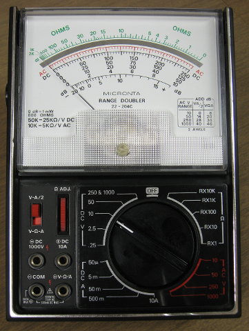
Or think of an old-fashioned analog multimeter with various scales marked. This 43-range one below was pretty special to me in the late 1970's when I was making under $4/hour and Radio Shack had them for $49.95 IIRC (which would be somewhere near $200 in 2014 dollars) and then they brought them down under $30 on sale, and I grabbed one! It was much better than what I had previously.
If you're on the .125V DC scale, each little mark in the top black row is 2.5mV, and you could further
interpolate to about 250µV by the position of the needle between the marks, like on a
slide rule. The mirrored scale is used to eliminate
parallax (although that's not to say the instrument's accuracy will match the precision). For each scale, you
have:
| full scale | each small mark | 10:1 interpolating |
|---|---|---|
| .125V | 2.5mV | 250µV |
| .25V | 5mV | 500µV |
| 1.25V | 25mV | 2.5mV |
| 2.5V | 50mV | 5mV |
| 5V | 100mV | 10mV |
| 10V | 200mV | 20mV |
| 25V | .5V | 50mV |
| 50V | 1V | 100mV |
| 125V | 2.5V | .25V |
| 250V | 5V | .5V |
| 500V | 10V | 1V |
| 1000V | 20V | 2V |
In spite of it being an analog meter, it has a range of about 4,000,000 to 1. Other than lacking a .5V scale,
any reading above 50mV can have a resolution of around 0.5% or better.
Consider the following reading:
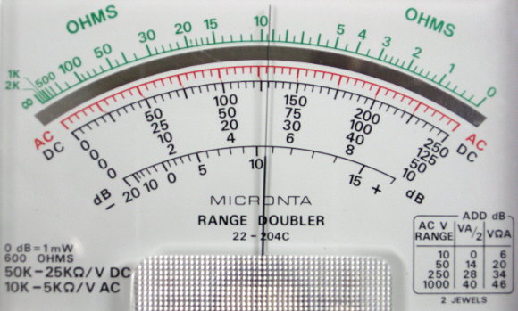
On the 125mV scale, it would be saying 64.8mV. On the 1000V scale, it would be saying 518V. If it were
on the 50mA current scale, it would be saying 25.9mA. You know by what scale you're in, by how you've set the
controls below. IOW, the user sets the scale to make the best use of the range of readings the meter can
give for the application. And so it is with scaled-integer math.
But now imagine a meter that allowed you to somehow stretch or contract the scales an arbitrary amount, so that for example if you wanted to measure something that would never exceed 7V, you could make 7V (or very slightly more) the right end of the scale, so you would get maximum resolution without changing scales!
Keep in mind that the scale factor in scaled-integer arithmetic does not necessarily have to be evenly divisible by 16, 10, 5, 2, or even an integer at all! (See the situation with degrees and radians further down.) Also, the six log and antilog tables can be used for any base, by scaling. In scaled-integer, they work best in base 2; but from there, you get the natural (base e) log for example by multiplying the base-2 log by 7050/10171 (or just cranking that number into the scale factor). The table descriptions page gives supporting information.
Of course you can make your standard single-precision cell to be more than 16 bits, like 20, 24, 32, etc.; but 16 works well for a lot of applications with 8-bit computers, and the tables provided here are for 16.
There's a Wikipedia article on binary angular measure (BAM) and "brads" (binary radians) here, and Jack Crenshaw addresses it in chapter 5 of his fine book "Math Toolkit for Real-Time Programming," ISBN 1-929629-09-5.
What about tangent, since the function has a nasty habit of going to ±infinity and
±90°? Just return the sin & cos both, as a rational number. Even infinity is
represented, because you can have the denominator (the cos portion) as 0. What you do with infinity is
your business <laugh>, but it can be represented!
You may be wondering about base conversions for when you want decimal input and output even though the computer internally uses hexadecimal. After all, we're also talking about handling things like decimal points and signs for input and output. It's not particularly difficult; and you can use the same routines to convert to and from any base, changing only the number in variable BASE. It does require multiplication and division, but you only do it when it's time for human I/O, and otherwise let the computer do its business efficiently in hex. The processor does not even need any decimal-mode arithmetic instructions like the 6502 & '816 have.
Here's an explanation of how, simplified not quite to the point of lying. It should give the basic understanding so you can write suitable routines. For inputting numbers from a text string (e.g. typed in from a keyboard), initialize a number as 0 to build on, then take the first digit in the string and add its value to the hex number you're building. Continue until you're out of digits, each time multiplying the build by the number in variable BASE and then adding the new digit's value to the build. If you encounter a decimal point, keep track of how many digits were after it. In the Forth programming language, the decimal point automatically makes the result double-precision; but you can convert back to single if you want to. If there was a minus sign, record that too.
For converting hex numbers to other bases for output (which will normally be a string), initialize a blank string. You will build it from right to left. Divide your number by what's in variable BASE, and use the remainder to add a text digit to the build, even if it's a 0. Keep doing that until there's 0 in the number. You can add a decimal point or other characters between digits, e.g. 12.345 or 12:36:40 (actually you might want to change BASE from 10 to 6 and back for the time readout, if you started with a number of seconds!)
The way Forth does this output number formatting is somewhat explained starting at about the middle of the page
of chapter 7 of Leo Brodie's
"Starting Forth" (with ANS updates here, and they're mostly calling single-precision 32-bit, like I want for the
65Org32 with all 32-bit
registers).
Subroutines or look-up tables could be made for virtually any function, scaling the inputs and outputs to take advantage of the resolution available in your standard cell size. The tables here have a standard cell size of 16 bits, or two bytes in an 8-bit computer.
You can download the files linked below, or I can supply 1Mx8 EPROM pairs with the tables pre-programmed into them. Many thanks to Tony (the late Nightmaretony on the 6502.org forum) for helping get them programmed on his Needham's Electronics EMP-10 programmer, and for donating some ST Microelectronics M27C801-100's for this. The price will only be what it costs to ship them. If you have questions or comments or find problems, please email me at the address at the bottom.
AboutHexFiles.html has a description of all
the hex files, including differences between similarly named ones and how to change the bank number if
desired. (I'm calling 64KB a bank, as on the 65816.) It could also be called "HowToUse.html"
because it also includes some helps on how to get the extras, like
Intel Hex is of course a text file, and most of the hex files here are 360KB in length, for 128KB of ROM space. The longest ones are INVERT.HEX and SQUARE.HEX at 720KB for 256KB of ROM space each. INVERT.HEX is partly for getting inverses (which makes division faster, because you can multiply by the inverse. Remember you can also divide by subtracting logs.) The byte order of two- and four-byte cells is reversed, ie, "little-endian," low byte first, for normal 6502 and 65816 operation, one of the things these processors do to improve performance.
   file name    table size    comments
   SQUARE.HEX     256KB    partly for multiplication.  32-bit output
   INVERT.HEX     256KB    partly for division, to multiply by the inverse.  32-bit output.
   SIN.HEX        128KB    sines, also for cosines and tangents
   ASIN.HEX       128KB    arcsines, also for arccosines
   ATAN.HEX        64KB    ends at 1st cell of LOG2.HEX (next)
   LOG2.HEX       128KB    also for logarithms in other bases
   ALOG2.HEX      128KB    also for  antilogs  in other bases
   LOG2-A.HEX     128KB    logs of 1 to 1+65535/65536 (ie, 1.9999847), first range for LOG2(X+1) where X starts at 0
   ALOG2-A.HEX    128KB    antilogs of 0 to 65535/65536 (ie, .9999847), the first range for 2x-1
   LOG2-B.HEX     128KB    logs of 1 to 1+65535/1,048,576 (ie, 1.06249905), a 16x zoom-in range for LOG2(X+1)
   ALOG2-B.HEX    128KB    antilogs of 0 to 65535/1,048,576 (ie, .06249905), a 16x zoom-in range for 2x-1
   SQRT1.HEX       64KB    square roots,  8-bit truncated output
   SQRT2.HEX       64KB    square roots,  8-bit  rounded  output
   SQRT3.HEX      128KB    square roots, 16-bit  rounded  output
   BITREV.HEX     128KB    set of bit-reversing tables, up to 14-bit, particularly useful for FFTs
   BITREV15.HEX   128KB    15-bit bit-reversing table (not included in EPROM)
   MULT.HEX       128KB    multiplication table like you had in 3rd grade, but up to 255x255

   MathTbls.zip            all the tables, zipped, including BITREV15.HEX which is not in the supplied EPROMs
   ROM0.HEX                a single Intel Hex file for ROM0 as I plan to supply it (also available zipped)
   ROM1.HEX                a single Intel Hex file for ROM1 as I plan to supply it (also available zipped)

                           --> The bottom of the table files' descriptions page has a summary of which
                               tables are in which EPROM, along with addresses in those EPROMs.
Since my own Needham's EPROM programmer software seems to have a bug in it for large files (and Needham's is out of business), I went on a quick search and found SRecord 1.65 for Linux and Windows. Initially I just wanted to confirm that my Intel Hex files were valid and error-free as far as Intel Hex goes; but this software also lets you transform/convert EPROM file types, concatenate, split, etc.. SRecord is command-line-only, which initially made it confusing because I didn't see any new icons and couldn't find it under "Applications". The voluminous .pdf manual linked on the page could stand to have better command-line examples, but you'll figure it out. Much of the manual is spent on telling about multitudes of file types you will never use, so there's really not that much that you have to read.
RationalApprox.html has some commonly needed rational-number (or fraction) approximations. The example of π (pi) was given above. Another example would be that you want to multiply by √2, so you multiply by 239, and divide the double-precision intermediate result by 169. The error of this pair is only -.00088%. If you want it closer, use 19601/13860. The error of this pair is only +.00000013%. And as always, integers still allow you to handle the remainder from the division for minimizing or avoiding rounding errors in especially the smaller numbers. RationalApprox.html also shows how I found the numbers using my HP-71 hand-held computer.
The automated test equipment (ATE) shown in my project pages on 6502.org did not use any floating point, even for logarithms (for dB). I didn't have the tables yet (and that much ROM took a lot more room back then), so I calculated them when necessary instead of looking them up.
CalcMethods.html, for the curious, tells how I calculated the
tables and formed the files using my HP-71 hand-held computer.
normal on-the-bus method: The easiest way is of course to just put the EPROMs on the bus, or load the files into RAM, if you have a processor with megabytes of address space like the 65816.
memory-map window into larger address space: In the case of a processor that only has a 16-bit data bus like the 6502, you could use a smaller window into a larger address space. When that window is addressed, the larger address space it looks into gets enabled, and output bits from your I/O ICs complete the higher address bits needed by the table memory. The window could be 256 bytes for example, for the low address byte of the EPROM bus on the other side of the window, and a couple of 8-bit output ports would feed the middle and high address bytes.
parallel I/O ports: Another possibility of course it to put it all on I/O ports, and write the address to the output ports and read the data from an input port. If the extra current drain from having one EPROM active all the time is not a problem, you won't even need to select and de-select them— just set the address and read it.
If that takes up all your parallel I/O, there's another solution. Read on.
Synchronous-serial: Computer already built up? Not enough memory space? Parallel I/O already taken? Don't want to wait until you can build your next computer to incorporate the look-up tables? Serial is of course not the first choice for speed, but it may be your ticket to implement the tables, and it's still well over an order of magnitude faster (not to mention more accurate) than having to actually calculate the math functions on a 6502. It takes 16 clocks' time to shift each byte of address and data, and, although we use delays for some of it, the processor can be getting the next byte ready to go while the current one is being shifted.
A solution that may not be so obvious is to use the synchronous-serial port of a 6522 VIA for example. If you have 6522, chances are, you haven't used the CA and CB pins for anything else anyway. To set the address, use SR (shift register) mode 110 (which you set in the ACR), shift out under control of Φ2, and to read the data, SR mode 010, shift in under control of Φ2.
Here's a diagram to show the idea, since the shift-register interface method is less well known among hobbyists:
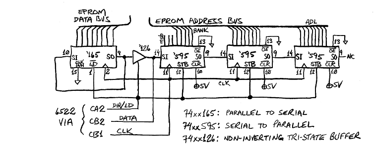
This circuit is almost identical to one I have working. It's msb-first in all cases, the 6522's SR, the 74HC165, and the 74HC595, so you don't have to reverse any bit orders, either in hardware or software. Set direction/load line (which you can put on CA2 of the 6522) low to shift out the address into the 595's, then set it high to read the data from the '165. The low-to-high transition transfers the '595 shift-register contents to the output latches, and the high level freezes the parallel input of the '165 and allows it to be shifted out. The high or low output of CA2 is set in the PCR, bits 3, 2, and 1. Use 110 for low output and 111 for high output.
The three 74HC595's give 24 output bits, a little more than any EPROM needs for address lines. If you use 1Mx8 EPROMs, you will need a couple of EPROMs, and they have 20 address lines. You could use a couple of the '595 output bits to select which EPROM you're reading instead of adding more address-decode logic, but I don't particularly recommend it because if you accidentally enable both EPROMs on power-up before the 595's are initialized, you'll have bus contention, along with possibly high currents and hot parts. Using the one additional address bit (for 21) and feeding the CS\ and OE\ of one of the EPROMs through an inverter to make sure they can't both be enabled at once would probably be best.
The reason you see the 165's output run back around to its input is that it is putting out the first bit (msb) before the first rising clock edge, then that first edge makes it put out the second bit, meaning you'll lose the first bit if you don't put it back around to the input and make it rotate around again. To deal with this, you can either connect the EPROM data lines to the 165's parallel input rotated over one bit position, or rotate it back into correct position in software with something like:
      PHA       ; Save a copy of the byte.
      ROR  A    ; Put bit 0 into C.
      PLA       ; Restore the original byte.
      ROR  A    ; Complete the 8-bit rotate.
the four instructions combined taking 11 clocks on a 6502. If a register is available, you can
replace PHA and PLA with TAX and TXA, or TAY and
TYA, for a savings of 3 clocks.
normal on-the-bus method: The details will depend on the hardware; but take for example the first hardware scenario above, where the memory containing the large look-up tables is directly on a 65816's bus. Then take a sine function, where in 16-bit scaled-integer math the angle is scaled such that 65,536 counts represents the full circle of 360°. The table has 65,536 answers pre-calculated, two bytes each, so the address of the answer will be twice the input value, plus the base address of the table (which, as supplied here, is $2:0000). So one way to do it is:
                            ; Start with the input number in the 16-bit accumulator.                  number of clocks:
SIN:     ASL  A             ; Double the input number by shifting left one bit position,                     2
         STA  TBL_ADR       ; and store the low 16 bits in the DP variable that we'll use as a pointer.      4
         LDA  #SIN_TBL_BANK ; Get the bank number where the table starts.                                    3
         ADC  #0            ; If the ASL above left the C flag set, increment the bank number.               3
         STA  TBL_ADR+2     ; Store it in the bank byte of the pointer variable.  (4th byte goes unused.)    4
         LDA  [TBL_ADR]     ; Read the sine value.  The two bytes of the answer will never straddle the      7
         RTS                ;                                                             bank boundary.
 ;------------------
The routine takes 23 clocks (2.3µs @ 10MHz), or 35 clocks (3.5µs @ 10MHz) if you include
the JSR & RTS pair. That is extremely fast compared to
having to calculate the sine function with a lot of multiplications and divisions!
There are different ways to do it. By not putting the accumulator temporarily into 8-bit mode, the above uses an extra byte in the direct-page variable (DP is like ZP on 6502, but movable on the 65816) for a total of four instead of three bytes, wasting a byte of DP memory in order to save a byte of program memory and three clocks' execution time. (REP & SEP each take two bytes and three clocks, and you won't make up that much by using a 8-bit accumulator to streamline the handling of the bank byte.)
memory-map window into larger address space: This scenario probably implies a 16-bit
address bus and 8-bit data bus like the 65c02 has. We can extend the above, something like this (on 65c02):
                             ; Start with the input number's low byte in A and high byte in Y.        number of clocks:
SIN:   ASL  A                ; Double the input number by shifting left one bit position.                    2
       TAX                   ; The low byte will be the index value in the 256-byte window into the          2
                             ;                                               larger table memory space.
       TYA                   ; Since you can't rotate in Y, transfer the input number's high byte to A,      2
       ROL  A                ; then rotate to continue the doubling into the next address byte.              2
       STA  TBL_ADR_MID_BYTE ; TBL_ADR_MID_BYTE is an 8-bit output port going to the ROM's address bits      4
                             ;                                                             8 through 15.
       LDA  #SIN_TBL_BANK    ; Get the bank number where the table starts.                                   2
       ADC  #0               ; If the ROL above left the C flag set, increment the bank number.              2
       STA  TBL_ADR_HI_BYTE  ; TBL_ADR_HI_BYTE is an 8-bit output port going to the ROM's address bits       4
                             ;                                                               16 and up.
       LDA  TBL_PAGE,X       ; TBL_PAGE is the address of the beginning of the page that is a window         4
                             ; into table memory.  Read the low byte of the answer into A,
       LDY  TBL_PAGE+1,X     ; and the high byte into Y.  (Doing the +1 on TBL_PAGE is faster than INX.)     4

       RTS
 ;------------------
The routine takes 28 clocks (2.8µs @ 10MHz), or 40 clocks (4µs @ 10MHz) if you include
the JSR & RTS pair. Curiously, it is not much slower than
the scenario above where the memory was actually on the µP's own wider bus! (The hardware is more
involved though.)
parallel I/O ports: The code for this is very similar:
                             ; Start with the input number's low byte in A and high byte in Y.        number of clocks:
SIN:   ASL  A                ; Double the input number by shifting left one bit position.                    2
       STA  TBL_ADR_LO_BYTE  ; TBL_ADR_LO_BYTE is an 8-bit output port going to the ROM's A0:A7.             4
       TAX                   ; If it's a write-only port, keep a copy to increment to read the answer's      2
                             ;                                                       second byte later.
       TYA                   ; Since you can't rotate in Y, transfer the input number's high byte to A,      2
       ROL  A                ; then rotate to continue the doubling into the next address byte.              2
       STA  TBL_ADR_MID_BYTE ; TBL_ADR_MID_BYTE is an 8-bit output port going to the ROM's address bits      4
                             ;                                                             8 through 15.
       LDA  #SIN_TBL_BANK    ; Get the bank number where the table starts.                                   2
       ADC  #0               ; If the ROL above left the C flag set, increment the bank number.              2
       STA  TBL_ADR_HI_BYTE  ; TBL_ADR_HI_BYTE is an 8-bit output port going to the ROM's address bits       4
                             ;                                                               16 and up.
       LDA  TBL_DATA_PORT    ; Read the low byte of the answer, then                                         4
       INX                   ; increment the low address byte (remember that no answer will straddle a       2
       STX  TBL_ADR_LO_BYTE  ; page boudary, so carrying is not a concern), and store it                     4
       LDY  TBL_DATA_PORT    ; and then read the high byte of the answer into Y.                             4

       RTS
 ;------------------
The routine takes 38 clocks (3.8µs @ 10MHz), or 50 clocks (5µs @ 10MHz) if you include
the JSR & RTS pair, so the speed is still not suffering much, and it
is still extremely fast compared to having to calculate the sine function with a lot of multiplications and divisions!
Synchronous-serial: First we do a one-time set up the 6522 VIA's SR and define a couple
of subroutines (I have not tried this 6502 code exactly as is, but it's mostly like something else that's already
working):
SR_SETUP:
        LDA  VIA_SR        ; Reset the 6522 VIA's shift register (SR),
        LDA  VIA_ACR
        AND  #11000011b
        STA  VIA_ACR       ; then move right into SR_OUT below.
 ;------------------
                           ;                                                                          number of clocks:
SR_OUT: LDA  #1100b        ; Put CA2 in output mode, outputting a low level to turn                          2
        STA  VIA_PCR       ; off the 74HC126 and put the '165 into load mode.                                4

        LDA  VIA_ACR                                                                                         4
        ORA  #00011000b                                                                                      2
        AND  #11111011b                                                                                      2
        STA  VIA_ACR       ; Put the SR in mode 110, shifting out under control of Φ2.                       4
        RTS                ; The whole subroutine takes 30 clocks, including the JSR-RTS pair.
 ;------------------

SR_IN:  LDA  VIA_ACR                                                                                         4
        ORA  #00001000b                                                                                      2
        AND  #11101011b                                                                                      2
        STA  VIA_ACR       ; Put the SR in mode 101, shifting in under control of Φ2.                        4

        LDA  #1100b                                                                                          2
        STA  VIA_PCR       ; Make sure CA2 is outputting a low to load data into the '165,                   4

        LDA  #1110b                                                                                          2
        STA  VIA_PCR       ; then back high to enable the '126 and shift the data out to the VIA SR.         4
                           ; RCV puts CA2 low again at the end, to turn off the '126.
        LDA  VIA_SR        ; Do a dummy read to make the SR start shifting.  The byte you read will be       4
                           ; left from shifting the address out.  There's no need to keep it.
        RTS                ; The whole subroutine takes 40 clocks, including the JSR-RTS pair.
 ;------------------
                           ; Actually, you could use 164's instead of 595's, then you wouldn't have to
CA2_HI_PULSE:              ; strobe them.  Reading the data will mess up the addr with 164's, but by then
        LDA  #1110b        ; the data will already have been loaded into the 165, so it shouldn't matter.    2
        STA  VIA_PCR       ; Make CA2 high                                                                   4
        AND  #11111100b    ; and then low again                                                              2
        STA  VIA_PCR       ; to strobe the address into the 74HC595s' output latches.                        4
        RTS                ; The whole subroutine takes 18 clocks including the JSR-RTS pair, which is
                           ; fine because when it's needed, we need to let a byte finish shifting.
 ;------------------

TBL_ADL:    DFS  1         ; One-byte variables: table address low, middle, and high bytes.
TBL_ADM:    DFS  1         ; Since we have to read twice to get two bytes, and feed the updated address
TBL_ADH:    DFS  1         ; between, we don't want to have to re-calculate the address.
TBL_DA_LO:  DFS  1         ; Data low  byte read from the table
TBL_BANK:   DFS  1         ; Starting bank number for table of interest.  Set up before calling 128KB_LOOKUP below.
                           ;                                                                          number of clocks:
128KB_LOOKUP:              ; Start with input number's low byte in A, high byte in Y, TBL_BANK set.
        TAX                ; Save A since SR_OUT writes over it.  (X is used again for something             2
        JSR  SR_OUT        ; else below too.)  Get ready to send the ROM address.                           30
        TXA                ; Restore the input number's low byte.                                            2

        ASL  A             ; Double the input number by shifting left one bit position.                      2
        STA  VIA_SR        ; Send out the low address byte of the ROM.                                       4
        STA  TBL_ADL       ; Also store it in a variable for later getting the 2nd data byte.                4

        TYA                ; Since you can't rotate in Y, transfer the input number's high byte to A,        2
        ROL  A             ; then rotate (with C flag) to continue the doubling into the next address byte.  2
        NOP                ; Give time to finish shifting low address byte out before giving it another.     2
        STA  TBL_ADM       ; While we're waiting, store the middle address byte for later getting the 2nd    4
        STA  VIA_SR        ; data byte.  Send out the middle address byte for the ROM.  It takes 16          4
                           ; clocks to shift 8 bits in or out.
        LDA  TBL_BANK      ; Get the bank number where the table starts.                                     4
        ADC  #0            ; If the ROL above left the C flag set, increment the bank number.                2
        JSR  end           ; Just JSR-RTS to give time to finish shifting this address byte out before      12
        STA  VIA_SR        ; giving it another.  Send out the high address byte for the ROM.  The JSR end    4
        STA  TBL_ADH       ; gave a little extra.  Now save the high addr byte for later getting the 2nd     4
        JSR  end           ; data byte.  JSR end again to give time to finish shifting hi addr byte out.    12

        JSR  CA2_HI_PULSE  ; Strobe the address into the 74HC595s' output latches.                          18

        JSR  SR_IN         ; Get ready to bring data in now, and do a dummy read to get data started.       40
        JSR  end           ; Give enough time for SR to finish shifting, then                               12
        LDA  VIA_SR        ; read the first (low) data byte.  (JSR end actually gives extra time.)           4
        STA  TBL_DA_LO     ; Store the first (low) byte of the answer.                                       4

        JSR  SR_OUT        ; Get ready to send the ROM address out again, although we'll increment it.      30
        LDA  TBL_ADL       ; Get back the low address byte we derived earlier,                               4
        INA                ; increment it to read the high byte of the answer, and                           2
        STA  VIA_SR        ; send it out the SR.  The address increment won't carry, because no answer       4
                           ; straddles a page or bank boundary.
        JSR  end           ; Again, give time to complete a byte shift before giving another byte to SR.    12
        LDA  TBL_ADM       ; Get back the middle address byte derived earlier, and                           4
        STA  VIA_SR        ; send it out to the SR.                                                          4

        JSR  end           ;                                                                                12
        LDA  TBL_ADH       ; Get back the high address byte derived earlier, and                             4
        STA  VIA_SR        ; send it out to the SR.                                                          4

        JSR  end           ; Need more time for shift to finish.  (This gives more than we need.)           12
        JSR  CA2_HI_PULSE  ; Strobe the address into the 74HC595s' output latches.                          18
        JSR  SR_IN         ; Get ready to bring data in now, and do a dummy read to get data started.       40
        JSR  end           ; Give enough time for SR to finish shifting, then                               12
        LDA  VIA_SR        ; read the first (low) data byte.  (JSR end actually gives extra time.)           4
                           ; (This listing is for data connections rotated one bit position as discussed
                           ; in the hardware section above.)
 end:   RTS                ; At the end, the high byte of the answer is in A and the low byte in TBL_DA_LO.
 ;------------------