It may seem late to be posting an RS-232 primer now that PCs usually come without RS-232 (COM) ports; but RS-232 still offers the attraction that it can be completely hand-built, programmed, and troubleshot by the technician or hobbyist. It is still common in industrial equipment. It may be slow compared to USB, but there are plenty of applications that don't need to transfer megabytes of data quickly (like video or hi-res pictures); and RS-232 is far more hobbyist-friendly than USB, and can be run much longer distances (which I address near the end of this page)!
This article is about RS-232, the common asynchronous serial interface. For a short description of synchronous serial interfaces, see this forum post which also tells about SPI, Microwire, dumb shift registers, I²C, SMBus, and 1-Wire.
I will give the main ideas of RS-232 interfacing, including things that are common practice but aren't in the technical specification. Other articles don't seem to give the info in the best order for a beginner. I add notes regarding the 6551 ACIA, since this is initially for 6502.org and its forum members. An article that has more on the connectors is available here, and of course there's the Wikipedia article. You will find lots of RS-232 links here.
Some will say that its real name is EIA-232; but if you really want to be up to date, it's
TIA-232-F. :D
The RS-232 so-called standard has been around for many decades. In spite of the confusion it produces, it has been a popular workhorse. It may seem like too many things about this "standard" are not standard at all. Much of what RS-232 started getting used for immediately (and is still used for today) is not what it was originally specified for, which is connecting modems (data communications equipment, or DCE) to other things like computers, terminals, and printers (data terminal equipment, or DTE).
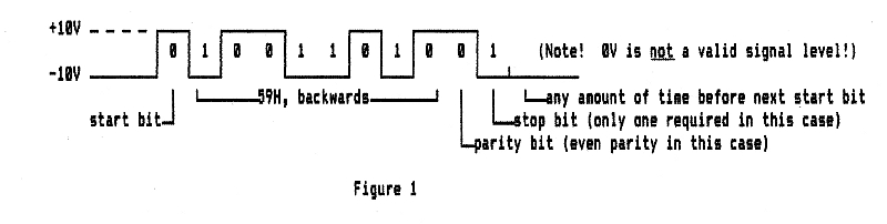
In RS-232, data is sent on a wire as a series of positive and negative voltages, one bit at a time (hence the word "serial"). Each frame begins with a start bit, which is followed by five to eight data bits (sent low bit first), followed by an optional parity bit for error-checking, and ending with one to two stop bits. Take figure 1 for example:
The X axis represents time. The first thing that you'll probably think looks wrong here is that the ones are the low voltage, and the zeros are high. It's not this way at the UART pins, but the line drivers and receivers invert it. Logic 1 is also called "mark". "UART" here stands for "universal asynchronous receiver/transmitter." Do not confuse this with the line drivers and receivers. The UART takes care of shifting the bytes in and out, generating the timing and the various housekeeping bits, detecting errors, and so on. The line drivers and receivers are just inverters that also serve as voltage translators between TTL logic levels and the ±10V (give or take a few volts) actually used on RS-232 lines. On a schematic diagram they are represented by the inverter symbol.
Before the frame can begin, the line has to be marking; ie, sending the voltage corresponding to "1". The transition to the 0, also called "space", for the start bit tells the receiver when the frame is beginning, essentially starting its timer. This time-reference edge is important because the only way the receiver knows which bit it should be receiving at any given time is by how long ago the start bit began. This is why it's called "asynchronous". The interface does not have a separate clock line to tell when to read the next bit. The receiver must keep time so it knows which bit it is receiving. Obviously the transmitter and receiver have to agree on how long a bit will last. That's where the baud rate comes in. More on that later.
After the eight data bits shown above, we have the parity bit. In this case, it's even parity. That means there has to be an even number of ones between the start bit and the stop bit. If there are an odd number of ones in the data bits, the parity bit gets set to make the number of ones even. The purpose is to check for errors. Obviously if you have two wrong bits (even if one of them is the parity bit itself), parity error-checking could be fooled; but it's unlikely that you'll have two wrong bits in the same frame if the data link seems to be working at all. Use of the parity bit is optional and not very common. If the data line is producing errors because of severe interference or any other reason, the UART will be reporting framing errors anyway.
The receiver looks for a "1" stop bit at the end of the frame. A framing error is reported when that stop bit doesn't come when the receiver expects it. The problem could be that the transmitter and receiver aren't set for the same speed, number of data bits, or whether or not to use a parity bit, or the cable may be picking up severe interference or simply be too long for the chosen speed, resulting in a very wobbly triangle wave instead of a clean set of high and low voltages resembling square waves. The RS-232 standard suggests that cables should not be more than 50 feet long; but this seems to be quite outdated, and people have run RS-232 hundreds of feet even at 115kbps. (See the paragraphs at the end after "About cable length:")
It's most common to use a single stop bit when using 7 or 8 data bits. 1.5 or 2 stop bits are generally used when the frame is very short from using only 5 or 6 data bits. After the full stop bit time, the next start bit can begin any time— assuming the receiver hasn't told the transmitter that it's not ready for more data yet. More on that later. If the transmitter is set for more stop bits than the receiver is, it will not cause any problems. The receiver will see the extra time marking as nothing more than a little blank time between frames. But if the receiver is expecting more stop bits than the transmitter is sending, an error condition is generated.
The MS-DOS command you might recognize as one that was common and typical for setting up a com port on a PC, "MODE COM2: 9600,N,8,1" sets com2 up for 9600 baud, no parity bit, 8 data bits, and 1 stop bit.
As you can see, a two-wire connection consisting of signal and ground is enough to transfer data in one direction. Since the voltages are high, and the source and load impedance are rather low, and the rise and fall times are not very fast for the length and capacitance of the cable we would probably be using to transfer data across a workbench, we can enjoy the fact that almost any cheap cable will do— even lamp cord. Adding one wire (to get three) is enough to have data going both directions, even simultaneously. The only caveat we have if more wires are not used is that the receiver must always be ready to receive data however continuously the transmitter will send it, unless a software protocol is used for the two ends to tell each other when they are or aren't ready for more data. (Such software handshaking will not be discussed here.)
We already mentioned framing errors and parity errors. If the receiving end cannot process the data as fast as it's coming, a byte which its processor has not yet read from the UART's receive buffer could get overwritten by a new byte coming in. Then the UART would signal an overrun error. These three—the parity error, the framing error, and the overrun error—are the three that the 6551 reports. The 6551 UART is also called an ACIA, for "asynchronous communications interface adapter." I've heard some say that the ACIA is a subset of UART functions, but others say there's no difference. The 6551 has all the UART features I can think of, and software-controlled, not set by jumpers or other hardware. You can find 6551 & 65c51 datasheets from the various manufacturers indexed here on 6502.org. There is also such a thing as a USART, or universal synchronous/asynchronous receiver/transmitter; so a UART would be a subset of USART functions.
We should mention that although UARTs are mentioned throughout this introduction, it is possible (as you probably already figured out) to do the UART job in software, doing what we call "bit-banging" with individual parallel port bits of I/O ICs like the 6522. "Bit-banging" is where the software handles the shifting, timing, error-checking, etc., instead of letting a UART do it in its hardware shift registers, timers, counters, and other circuits. I believe the Commodore 64 did it with a 6526 (which is a general parallel-I/O IC). Note that this is not referring to its IEC bus which is synchronous serial and is brought out through a DIN connector. A bit-banged UART should only be considered a last resort however. (There is a forum topic here on bit-banging 57,600bps on a 1MHz 6502.) Using a real UART is much easier from the programming perspective, usually allows higher speeds, and allows the processor to work on other things between byte transmissions or receptions. Don't confuse asynchronous serial (like RS-232) and synchronous serial (like SPI, Microwire, and I²C). Synchronous serial interfaces with their separate clock line usually do not have the tight timing requirements that RS-232 does, so they're much easier to bit-bang if you have to, and to do so at comparatively high speeds.
Back to baud rate. The baud rate on this kind of communications interface is generally the same as the number of bits per second, since RS-232 doesn't try to encode more than one bit per time period. 9600 bits per second (bps), or 9600 baud, is one of the more common baud rates. Most UARTs have speeds as slow as 50 bps in their standard choices. (Why so slow, you might ask? One application might be radio links where the signal is extremely weak, and the receiver may need to use an extremely narrow bandwidth to filter out interference and noise.) Above 150 bps, you keep doubling the number to get up to the next common baud rate: 150, 300, 600, 1200, 2400, 4800, 9600, and 19200. The "standard" RS-232 rates between these numbers (1800, 3600, 7200, 14400) are rarely used. A common speed above 19200 is 115,200 which is six times the 19200, and eight times that number is 953,600. A few in between, including 38,400, 57,600 (which is three times 19200), and 230,400, are less common.
Since we're talking about bits per second, the amount of time, in seconds, for each bit is 1/baud. At 9600 baud, you get 104.2 microseconds per bit. If the speed of the transmitter and receiver disagree by more than 2-3%, the errors will start showing up. 5% would be a half bit time by the end of the frame. If the transmitting end were 1% below the intended speed and the receiving end were 1% above the intended speed, you would have just about all the error the system could tolerate and keep working reliably under ideal conditions. To avoid problems in this area, the UARTs' speed is normally crystal-controlled for accuracy.
The maximum speed supposedly allowed by the original RS-232 specification was 20kbps (kilobits per second); but with faster rise and fall times and care in the cabling, some products like Diva Automation's SuprChip (which used the 6502) run RS-232 at up to half a megabaud (500,000bps) or more. Using a standard 1.8432MHz crystal or external oscillator, the 6551's highest bit rate in the sequence of standard rates is 19.2kbps, and then there's a gap between there and 115.2kbps which you can get by clearing the four lsb's of the control register to 0 so it will take the crystal frequency and divide it by 16 to get the bit rate. The '51 is guaranteed to be able to go at least 125kbps if you use a 16x external clock source which is the normal way for it to give the 31.25kbps required for MIDI, or musical instrument digital interface. You can use a 65c22 VIA's PB7 output automatically toggled by the timeout of the VIA's T1 timer, with no further attention from the processor, to get this clock source for the higher standard bit rates on a 65c51 ACIA, still controlling the speed in software, with no extra hardware. See how, near the bottom of the I/O ICs page of my 6502 primer.
Added Oct 7, 2018: GGLabs' GLINK232 aftermarket board for the Commodore 64 and 128 uses a 65c51 with a 3.6864MHz (ie, double speed) crystal so all the baud rates are twice what the ACIA's data sheet says. According to this forum post, even early 6551's have been successfully used this way in several designs. I'll update this if I find out more.
If you use the common configuration of start bit, 8 data bits, no parity bit, and 1 stop bit, you have 10 bits in a frame, so the number of bytes transferred per second is generally the baud rate divided by 10 if there are no delays between frames. 9600 baud makes for a maximum data transfer rate of just under a thousand bytes per second.
In order to make the receiving part of the UART more immune to random spikes and other interference, many UARTs (including the 6551) sample the received data voltage many times per bit period, and then "take a vote," so to speak. This improves the trustworthiness of the received data.
So far we have only talked about the data lines. There are also hardware handshake lines whose functions are addressed further down. They use the same voltages, loads, etc., but they refer to status and don't carry timed bits of data.
The transmitting standard goes like this: Logic 0 is +5V to +15V. Logic 1 is -5V to -15V. -5V to +5V is the transition area. Transmitters can handle indefinite shorts to each other or to ground without damage. Again, the voltages seem backwards; but it's because the line drivers and receivers invert the signal.
Powering the line drivers from ±12V used to be pretty standard, but line drivers like the MC145407 and the well known MAX232 and its many relatives use internal switched-capacitor voltage converters and multipliers to get (almost) ±10V from a single 5V supply. Still, if you have ±12 (or something in that neighborhood) on the board to power the line drivers, ones like the 1488 or MC145406 (same thing as the SN75C1406) take less board space, because they don't need external capacitors and the extra pins to connect to them.
For low-power hand-held applications where battery power is saved at all costs, it is also possible to power the line drivers with power taken from the receivers' input signals. A unit designed like this would have to be connected to another computer that will supply the power. Obviously it won't work if it is connected to another one of the same which also supplies no power, especially if you have a hand-held terminal with no power source of its own.
The receiving standard goes like this: Logic 0 is +3V to +25V. Logic 1 is -3V to -25V. -3V to +3V is transition area. Specified impedance for one receiver load is 3KΩ to 7KΩ. One output can usually drive quite a few inputs (and LEDs for troubleshooting).
To reduce problems with noise and interference, the receiver usually has some hysteresis to keep its output steady at the last valid logic level while the input is crossing that transition area, and then outputs a fast edge to the UART when it does go to the other logic level.
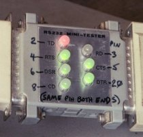
Again, remember that logic 1 = true = "mark" = hi = negative voltage, as mixed up as that may seem; and logic 0 = false = "space" = lo = positive voltage. I have found Jameco's 7-LED tester, cat. no. 26729, to be very helpful in quickly troubleshooting basic RS-232 problems. Each of the seven major lines is connected through a resistor to a bi-color LED to ground. The LED lights up green if the voltage is above ground (meaning a logic 0), and red if the voltage is below ground (meaning a logic 1). When no data is going across but all handshaking lines are in the true state (ie, both ends are ready to send and receive), the TD (transmit data) and RD (receive data) LEDs will be red, and all the others will be green.
Handshake lines: Ok, so we mentioned that there are other connections besides ground and one for data
each direction. You might wonder why the DB-25 connectors that are so commonly used for RS-232 have so many (25) connections.
What's the point? Well, actually they are all defined in the standard except for four (pins 9, 10, 18, and 25) which are
reserved. It's rare to see more than "the big 8" in use though.
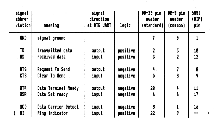
Remember we had alluded to ways for one piece of equipment to tell the other one whether or not it is ready to accept more data. This is often done in hardware, using more wires. "The big 8" include not only a ground wire and a pair of wires for data (one wire carrying the data signal for each direction), but also two pairs of "handshaking" lines, and one other line which is normally only used by modems. The big 8 (plus one more) are:
(For a boat load of other RS-232 pinouts used for different connectors by various companies, see http://www.conserver.com/consoles/Signals/signals.html.)
The signal names and DB-25 pin numbers shown are for DTE (data terminal equipment), which basically means everything except modems (which are DCE, or data communications equipment). The signal abbreviations at the UART itself have the bar over them (meaning negative, or inverted logic) for all but TD, RD, and RI.
Remember that there will be inverting line drivers and receivers between all the 6551 pins numbered above and the RS-232 lines themselves. There are many other UARTs besides the 6551; but since this description is for www.6502.org and many of the hobbyists there are still using this UART (or ACIA), the pin numbers in the chart should be helpful. WDC (that's Western Design Center, not Western Digital!) is the prime 65c51 supplier at the time of this edit (April 2012).
Edit, 2/8/19: I think 6502.org forum member GaBuZoMeu has the best solution yet: Use the 51's pin 5 (if in DIP), the x16 clock, as an output to drive a VIA's PB6 for its T2 to count pulses and generate an interrupt. The T2 latch value does not need to change with Φ2 rate nor with baud rate.
Edit, 12/18/23: Forum member John_M had another idea, which was that if you have a '51 RxD (or other UART RxD input) that's free, you could use it to monitor the TxD output of the buggy chip, and use the 'RxD register full' interrupt to indicate that the byte has been sent.
Here's the idea. RTS was originally for putting a half-duplex modem into transmit mode. In other words, the computer is saying, "I have data to send. Please get ready to send it for me." CTS told the computer when the modem was ready to send (possibly having had to wait to finish receiving some data first). Well, like so much of today's RS-232 implementations, that specification broke down. The function that RTS more commonly takes on today is to tell the device at the other end of the line, "Go ahead and send data. I'm ready to take it." Then the function that CTS more commonly takes on is to know if the device at the other end of the line is ready to receive data.
DTR was used by many DTE devices to take the modem on- and off-line. One effect is that it can tell the modem whether the computer (or DTE) is able to accept an incoming call. DSR tells the DTE that the modem is connected, powered up, and ready to go; ie, not in talk, test, or dial mode. When neither end of the line is connected to an actual modem, these lines generally tell the device at each end that the device at the other end is ready for business. So in that case, what becomes of the difference between these and RTS/CTS? Not much; but if the sending end tends to send data faster than the receiving end can process it, the receiving end will be constantly toggling its RTS output, not its DTR output. The RTS output will go to the sender's CTS input to turn the data-sending off and on such that we don't get the overrun errors previously mentioned. Many of the newer UARTs don't even implement DSR & DTR at all, only RTS & CTS, and of course TD & RD.
DCD is used to let the computer know that the modem is receiving a carrier of adequate quality for dependable communication. RI may be used by an auto-answer modem to tell the computer that there's a ring signal on the phone line. The computer may then use DTR to tell the modem to answer the call. In the case where neither end of the line has a modem on it, DCD is often just connected to DSR, and RI is left unconnected.
The 6551 ACIA (UART) will not send data if CTS is not true, and it won't receive if DCD is not true. This doesn't mean you absolutely have to use CTS and DCD. If you only want a two- or three-wire interface with no hardware handshaking, then ground these UART inputs so the 6551 will run.
A note should be made here regarding CTS and the 6551. An applications note I have here for the Synertek NMOS 6551, as well as the '87 Rockwell data book's NMOS 6551 pages say that transmission of an already-started frame will stop immediately when CTS is taken false, the byte will be lost, and the TD line will go to marking. I consider this to be either a serious bug, or an idiotic part of the original NMOS design. The same Rockwell book says that the CMOS 65c51 will finish the already-started byte before halting transmission after CTS goes false. (IOW, they corrected that problem when they did the CMOS design.) The other data sheets I have only say CTS must be true for the ACIA to transmit, without giving details of what happens when CTS is taken false in the middle of a frame. My expectation then is that regardless of brand, the CMOS ones generally will finish the frame whereas the NMOS ones won't. If it matters in your use, you will want to experiment with the particular brand of 6551 you have in order to make sure your program operates it correctly so as not to lose data. If the NMOS 6551 is interrupted during a frame transmission, the program will have to give it the same byte again to transmit when CTS goes true. I have used a couple of different brands of 65c51 (ie, CMOS) for decades and never had that trouble with it. In fact, everything I've ever done with the 65c51 worked on first try, except when I lacked a capacitor in the crystal circuit. (If you're using just a crystal and not a separate oscillator, the crystal goes from pin 6 to pin 7 of the DIP, but you need a 22pF capacitor from pin 6 to ground.) The only thing I don't like about the 65c51 is that a couple of the controls are merged into the same control bit, where it would be nice to be able to control them separately instead. (Caveat: I have not used WDC's 65c51 which has a different transmit bug mentioned six paragraphs up.)
The 6551's other three handshaking lines don't necessarily have to be used either; but the inputs should not be left unconnected. It would be best to ground them if they're not connected to line receivers. If you're making the computer yourself, you may want to use pin headers so you can put jumpers on the appropriate pairs of pins to select whether or not to use CTS and DCD. If you're using the full complement of hardware handshaking, you'll want those inputs to be fed from the connector pins through the line receivers. Otherwise, you'll want one or both of these UART pins to artificially be held true by grounding them.
I've seen the handshaking lines used for other things besides RS-232. One example is the serial PIC microcontroller programmers which manipulate the host computer's RS-232 handshaking outputs to make the clock and data lines for the synchronous-serial interface. That's a different ball of wax which I will not cover here.
Near the end of my interrupts primer, under the section title "Interrupt support for RS-232 receive" there's some example 6502 code on running an RS-232 receive buffer using a 6551, and on setting up the 6551 for the job.
Solving problems: Now you see the fun beginning. There's room for confusion at every
turn. Welcome to the world of RS-232. It may all look like a disaster, but it's usually not really that hard to get
things working together. As we said before, most RS-232 implementations today don't have a modem at either end of the
line. Both ends of the line are generally DTE. You no doubt noticed that if the connections are made straight across,
you'll have the TD output of one device connected to the TD output of another. Likewise, the RD inputs of the two will be
connected together, and the handshaking lines, the same.
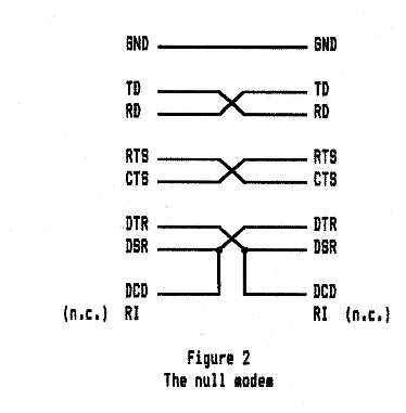
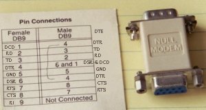
Obviously you'll need to cross the TD and RD lines so an output goes to an input and vice-versa. What should be almost as easily understood above is that the same can be done with RTS and CTS. It may not be quite as clear, but generally the same can be done with DTR and DSR. But instead of having cables that cross the lines between connectors at the ends and other cables that don't (to serve as extension cords), one way to get things straight is to insert a null modem somewhere along the line.
A null modem is simply a pair of connectors that cross these lines, as in figure 2:
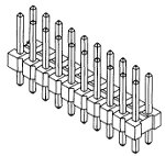
If you're making your own computer board and anticipate the need, you might add pin headers to make the more common DB-25 or DB-9 (actually DE-9) connector pinouts selectable by putting the shorting blocks onto the right pairs of header pins. (The B or E or other letter refers to the shell size, and the 9-pin in normally in the E-size shell, and the 25 in the B-size shell.) It could be done with DIP switches too, but they take more room. By "pin headers," I mean this kind of thing:
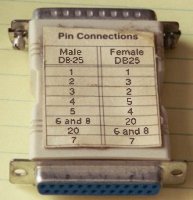
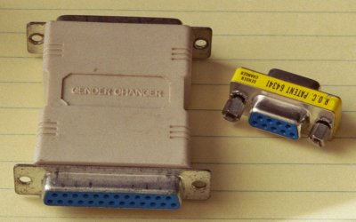
Another frequent problem is simply the connector genders. Gender changers are easily available with either two female connectors or two male connectors:
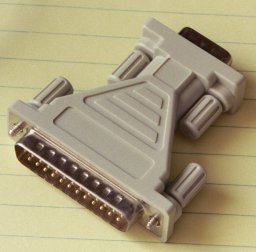
Adapters are also easily available to go from DB-25 to DB-9 (actually DE-9):
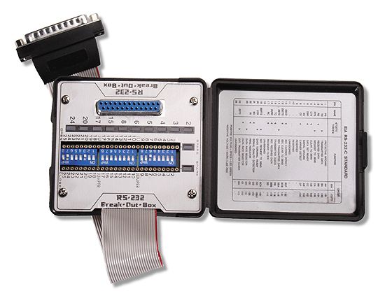
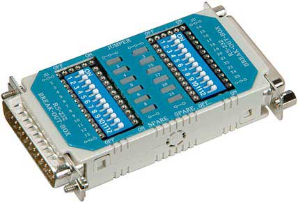
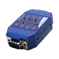
If you need to "trick" the interface more than this and need to do some experimenting to figure it all out before making up a special cable with unconventional connections, you can use a break-out box. These give you the possibility of trying various connections quickly and without soldering. They usually have an array of LEDs on them as well so you can immediately see what effects you're producing. Here is one from Specialized Products, their 450X150 (this one and this one seem to be the same thing), followed by a couple from Advantech (formerly B&B Electronics) and Assmann:
Here are a couple of testers, first Jameco's 26729 , then B&B Electronics'
(now Advantech's) 9PMTT
:
Consider these simple examples of how the LEDs help to quickly troubleshoot a connection. If one end of the cable is connected
to a COM port on a PC and the PC's handshaking outputs' LEDs are red, you probably forgot to set up the PC's port. If the only
LEDs to light up are those for the outputs of the device at one end of the cable, it probably means you need to insert or
remove a null modem, because outputs are talking to outputs and inputs are listening to inputs, instead of vice-versa. If data
does not keep going, you may see the a CTS or RTS LED light up red, possibly meaning that your program is taking in enough
data to fill a buffer in RAM, but then not processing that data— or maybe it processes it but you forgot to make it update the
buffer pointers and tell the UART that it's ok to accept more data.
I'll put this here for lack of a better place: When servicing 6551 ACIA interrupts for simultaneous transmission and reception, remember that reading the status register clears the interrupt, but the interrupt could have been caused by both TX register empty and RX register full at the same time. If your ISR ends before finding all the interrupt causes, it may, for example, find the receive register full, service that, and then exit thinking it's done, when in actuality the transmit register emptied before you read the status register and it's waiting for the next byte. Now the IRQ line is false and the issue will never be addressed, and transmission will come to a halt. If more than one thing in the same IC could need service, make sure the ISR doesn't stop before the whole job is done. This is from my tip #14 in my "Tip of the Day" column.
Some IC choices: Many UARTs today (for example, the MAX3100) only implement TD, RD, RTS, and CTS,
as this is usually enough. If you're using one of these UARTs and really need the other lines, you would have to get those by
using a few I/O bits of a parallel port of another IC like a 6522 VIA.
Remember the line drivers and receivers go between the DB-25 connector and the UART. The voltages on the connector side are generally ±10V (give or take a few volts), whereas the voltages at the UART pins are TTL levels (0-5V, or less). The line drivers and receivers are also inverters, and they generally are much more immune to damage from static discharge than the UART is.
The well known Maxim MAX232 has two line drivers and two line receivers. It is popular because it was one of the first widely available line driver and receiver ICs that derived its own high voltages from the +5V supply so the user didn't have to provide more than one power supply voltage. It should be noted however that there are many other line drivers and receivers. Before the MAX232 came along, the 14-pin 1488 (75188) quad line driver and 1489 (75189) quad line receiver were usually used, both $.29US in singles at Jameco at the moment, or the SN75C1406 (same thing as the older Motorola MC145406), a $2 16-pin IC with three line drivers and three line receivers. With a 1488/1489 pair, you have four line drivers and four line receivers, just as you have with two of the higher-priced MAX232's, and they take less board space because they don't require the capacitors for charge pumps like the MAX232 does, or the extra pins to connect to the capacitors. The extra power supplies needed by the 1488 and SN75C1406 (same thing as the MC145406) are often available on the board anyway for other things like op amps, D/A and A/D converters, and the negative voltage for supertwist LCD bias. Again, remember the voltages are not critical. For example, if you have +9V and -7.5V, it should work. I've used a pair of 9V batteries for ±9V power supplies.
It should be noted here that the 1489 has an extra input pin for each of the four receivers. This can be used for changing the input threshold voltage or for increasing input noise immunity. In most cases, these pins can be left unconnected.
It should also be noted here that each of three of the four line drivers in the 1488 has two inputs. If either one is pulled low, the output will go to the high voltage. In most cases, the extra input can be left unconnected.
Construction with the connectors: Unfortunately the DB-9 & -25 pin spacing is .109" and rows are
staggered so they don't fit nicely into .1"-grid perfboard. The pins of a right-angle DB-9 can sometimes be bent enough to get
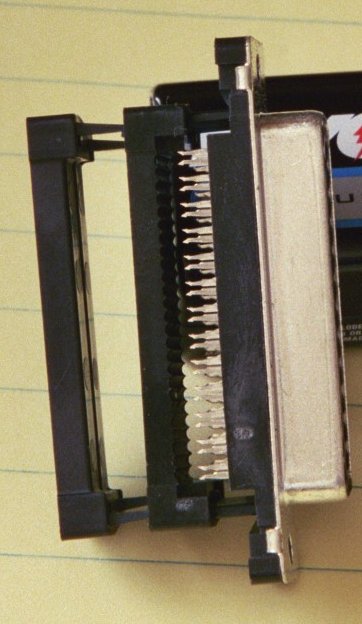
them into the holes in the perfboard, but you won't be so lucky with the DB-25. One way to solve the problem is to use a soldercup
DB-25 that is intended to be mounted on a cable, and mount it on the board with two tiny L-brackets at the ends, then solder to
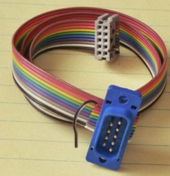
it. Another solution is to put a dual-row pin header on the board, and then prepare a ribbon cable with a standard 26-contact
IDC (insulation-displacement connector) at one end and a DB-25 that's made to be mounted on ribbon cable at the other end.
For three-wire interfaces (with no hardware handshaking), I have even used 3-conductor mini phone jacks and plugs, using the tip for output, the center ring for input, and the sleeve for ground. It's not standard, but it sure takes less room on the board!
About cable length: The original RS-232 specification was for 50 feet maximum cable length. That's
rather toothless though, as it depends on the cable, data rate, and line driver, and the specification did not say anything about the
cable itself.
At http://aplawrence.com/Unixart/serial.art.html,Tony Lawrence says,
In this forum post, BDD tells of his experience cabling a paint factory in 1997, and says,
May 2019 note: I'm working with a module now whose UART goes up to 4Mbps—although I doubt it's intended to be put through RS-232 line drivers and receivers to go any significant distance.
If these specs aren't enough, you can go to RS-422 or RS-485 which are differential (balanced), and the output can come from 5V or 3V drivers since the inputs can tolerate up to 6V and you only need 200mV difference between the two wires to get a valid logic level. Here's the idea, showing transmitting $D3:
Note that the start and stop bits, and the bit order, are the same as commonly used with RS-232, so the only things that are
different are the line drivers and receivers, and the cabling and connectors. You can use the same UART, and see basically the
same things on an oscilloscope if you use one for troubleshooting.
RS-422 and -485 can go both much farther and much faster than RS-232. RS-422 can do 10Mbps at 40 feet, and RS-485 can do 35Mbps at 33 feet, which is nearly three times the speed of USB 2.0, and at twice the distance! Both RS-422 and RS-485 can go at least 90kbps at 3/4 mile. A rule of thumb for RS-485 max speed versus cable length is that the speed in bit/s multiplied by the length in meters should not exceed 10^8. Thus a 50-meter cable should not signal faster than 2 Mbit/s.
As a final word, I might add that once you have working RS-232 ports on your project, you can connect to a wide range of devices
not limited to just the obvious PC interface, mouse input, etc.. Companies like
Advantech (formerly B&B Electronics)
and
Patton Electronics make interface converters
that will translate RS-232 to IEEE-488, RS-422, RS-485, and other standard interfaces.
Startech makes RS-232 boards for your
PC (if you have something like a mini tower case) to give you RS-232 port without going through USB.
Some of the tips in the "Tip of the Day" forum topic are about the 6551 ACIA, specifically tips #6, 10, 11, 13, 14, 22, and 23.
Added 1/21/19: Here's a WiFi modem that can provide internet access to any computer with an RS-232 serial interface. The GuruModem also has an onboard SD-card interface to allow local backup of data downloaded from the internet. Full flow control is provided for speeds up to 115.2kbps. See https://electronicsisfun.com/f/gurumodem--the-gold-standard-in-rs-232-wifi-communications.
Bibliography:
        The RS-232 Solution
        by Joe Campbell
        © 1984 Sybex Computer Books, in Alameda, CA

        Datatracker DT-4 Operator's Manual and Interfacing Guide, version 3.0, Oct 1986
        Datatran Corporation in Denver, CO
        Chapter 3 gives RS-232 background.  I expect the manuals of several other RS-232
          break-out boxes and testers would also have similar explanations.
Other books that should prove helpful:
        Data Communications: A Comprehensive Approach
        by Gilbert Held and Ray Sarch
        McGraw-Hill Publications Co.

        Understanding Data Communications
        by George E Friend, John L. Fike, H. Charles Baker, and John C. Bellamy
        Texas Instruments

        RS-232 Made Easy: Connecting Computers, Printers, Terminals, and Modems
        by Martin D. Seyer
        Prentice Hall Inc.

        Computer Communications Techniques
        by E. G. Brooner and Phil Wells
        Howard W. Sams & Co., Inc.
Originally written in 2003, last updated Aug 15, 2024 Garth Wilson
wilsonminesBdslextremeBcom (replace the B's with @ and .)